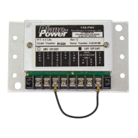
R1224 Regulator
Installation Instruction
12-1001 24-30-01
Rev. M: 01 Dec. 2021 Page: 6-7
© 2021 - Hartzell Engine Technologies - All rights reserved
6.6 Regulator Installation Guide-C
A. General
Use R1224 and 12-1021 Adaptor Plate.
These regulators were connected via 5 color-coded wires. Cut the wires near the regulator and crimp the
provided ring lugs onto the wires.
(1) Remove old regulator.
(2) Ensure that the R1224 jumpers are set properly for the aircraft voltage (Fig. 6-1). Verify aircraft electical
system voltage.
(3) Install R1224 using 12-1021 Adaptor Plate.
(4) Connect the Black wire to R1224 #1 (GND).
(5) Connect the Blue (Field) wire to R1224 #2 (FIELD).
(6) Connect the Red (Power) wire to R1224 #3 (ENABLE).
(7) Connect the Yellow (Lamp) wire to R1224 #5 (LAMP).
(8) If applicable for LAMP function, connect a locally manufactured jumper between R1224 #3 (Enable) & #4
(Aux).
(9) For R1224 Rev B and earlier: Insulate the end of the Orange (Sense) wire and stow it safely.
For R1224 Rev C and later: Remove jumper between #8 (SENSE) and #3 (ENABLE). Connect the
Orange (Sense) wire to R1224 #8 (SENSE).
(10) Insulate the end of the White (OV Lamp) wire and stow it safely. (The R1224 indicates Over Voltage and
Low Voltage on a common lamp connected to R1224 #5.)
(11) Adjust voltage as necessary with engine running and alternator enabled.
6.7 Regulator Installation Guide-D
A. General
The Ford regulators were connected via a at plastic plug. Label the wires and cut the plug o. Marking the
wires is important for reconnection. Crimp the appropriate ring lugs onto the wires.
(1) Remove old regulator.
(2) Ensure that the R1224 jumpers are set properly for the aircraft voltage (Fig. 6-1). Grumman AA-5, AA-
5A and AA-5B are 14V. Single-engine Cessna aircraft were 14V or 28V – Verify aircraft electical system
voltage.
(3) Install R1224. The large holes in the base match the mounting holes used to mount the Ford regulator.
Some mounting locations may have protrusions under the regulator, as the Ford units had a hollow area
underneath. If this is the case, mount the R1224 on standoffs or use the 12-1021 Adaptor Plate. The 12-
1021 can be purchased from Plane-Power.
(4) Connect the G (Ground) wire to R1224 #1 (GRND).
(5) Connect the Blue (Field) wire to R1224 #2 (Field).
(6) Connect the S (Supply) wire to R1224 #3 (ENABLE).
(7) If applicable for LAMP function, connect a locally manufactured jumper between R1224 #3 (Enable) & #4
(Aux).
 Loading...