40 Liquidus Tracker
3.2.2.1.2 Single solution mode
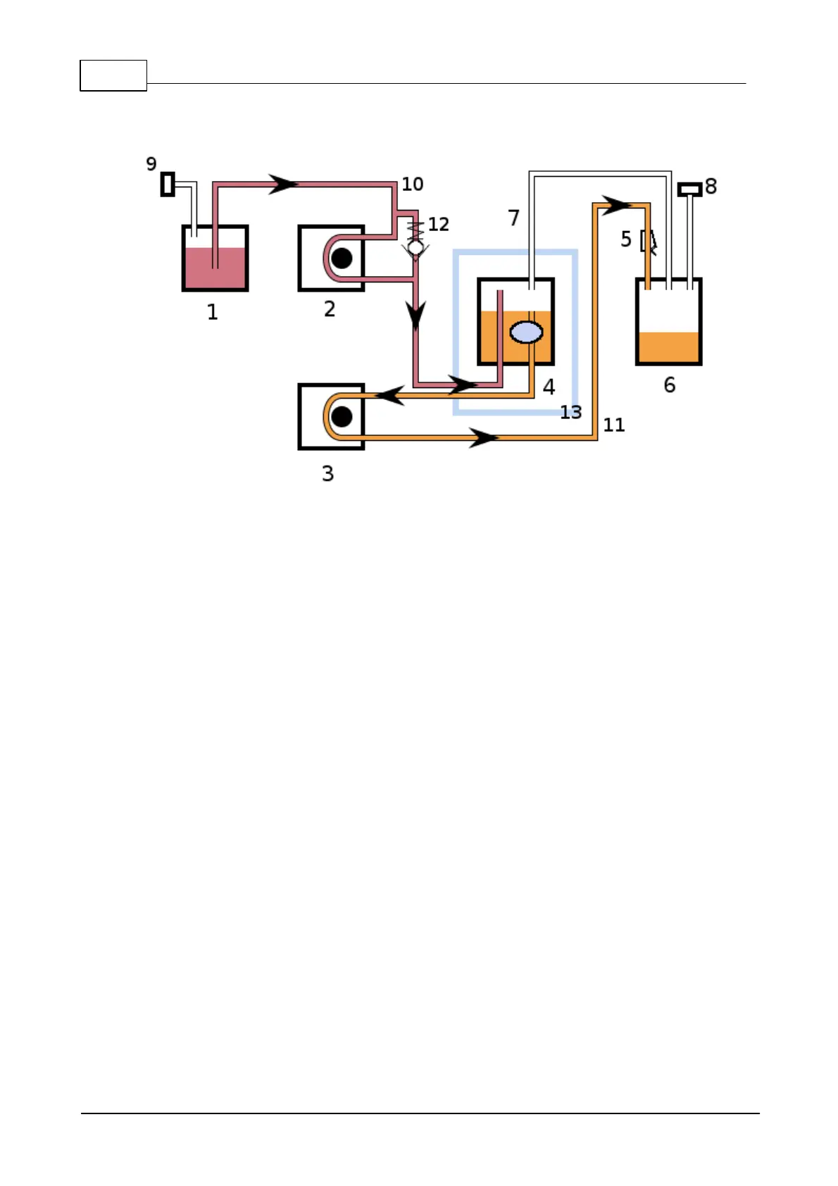
The basic flow system is simplified as shown in the diagram below.
1. DMSO solution Ksol1%
2. Peristaltic pump 1 running at F1 mL/min/rpm
3. Peristaltic pump 2 running at F2 mL/min/rpm
4. Sample container
5. Extraction clamp
6. Waste collection container
7. Pressure relief tube
8. Filtered exhaust vent
9. Filtered inlet vent
10. Injection line
11. Extraction line
12. Pressure relief valve
13. Boundary of the chamber
In this system, one solution is pumped by a peristaltic pump into the sample container for a period
defined by Tstep.
The sample is left to stand for a short period defined by the Tstand parameter.
Finally a second peristaltic pump extracts the same volume of liquid that was introduced by the first
pump. This extraction is completed in the time defined by Tstep x 7. The extraction step is 7 times