10
2.6 Wiring the Fault Alarm Contact
The fault alarm contacts are in the middle of the terminal block
connector as the picture shows below. Inserting the wires, the
Industrial Gigabit Ethernet Switch will detect the fault status of
the power failure and then forms an open circuit. The following
illustration shows an application example for wiring the fault
alarm contacts.
1 2 3 4 5 6
Fault Alarm Contacts
The Fault Alarm Contacts are
energized (CLOSE) for normal
operation and will OPEN when
failure occurs
Fault
Insert the wires into the fault alarm contacts
Note
1. The wire gauge for the terminal block should be
in the range between 12 and 24 AWG.
2. Alarm relay circuit accepts up to 30V, max. 3A
currents.
2.7 ProductSpecications
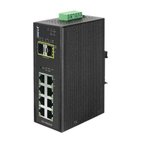
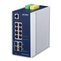
Model IGS-1020TF
HardwareSpecications
Copper Ports
8 x 10/100/1000BASE-T RJ45 TP
Auto-MDI/MDI-X, auto-negotiation
 Loading...