- 9 -
- 10 -
- 11 -
- 12 - - 13 - - 14 -
Note
The wire gauge for the terminal block should be in the
range between 12 and 24 AWG.
Note
1. The power input range is 12V ~ 48V DC for IGS-
500T, 9 ~ 48V DC for IGS-510TF and supports 24V
AC.
2. Use one power input when using 24V AC.
3.5 Wiring the Fault Alarm Contact (IGS-500T Only)
The fault alarm contacts are in the middle of the terminal block
connector as the picture shows below. Inserting the wires, the
Industrial Gigabit Ethernet Switch will detect the fault status of
the power failure and then forms an open circuit. The following
illustration shows an application example for wiring the fault alarm
contacts.
1 2 3 4 5 6
Fault Alarm Contacts
The Fault Alarm Contacts are
energized (CLOSE) for normal
operation and will OPEN when
failure occurs
Fault
Note
1. The wire gauge for the terminal block should be in
the range between 12 and 24 AWG.
2. Alarm relay circuit accepts up to 24V DC, 1A.
4.1 DIN-rail Mounting Installation
1
2
4.2 Wall-mount Plate Mounting
4.3 Side Wall-mount Plate Mounting
(IGS-510TF Only)
Caution
You must use the screws supplied with the wall-
mounting brackets. Damage caused to the parts by
using incorrect screws would invalidate your warranty.
3.6 Grounding the Device
Users MUST complete grounding wired with the device; otherwise,
a sudden lightning could cause fatal damage to the device.
V1+
V1-
PWR1
V2+
V2-
PWR2
DC Input: 9-48V , 0.6A max.
AC Input: 24V , 0.3A max.
1 2 3 4
Earth Ground
Note
EMD (Lightning) DAMAGE IS NOT CONVERED UNDER
WARRANTY.
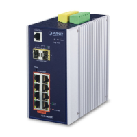
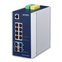
4. Installation
This section guides you to installing the Industrial Gigabit Ethernet
Switch on the DIN rail and wall. Please read this chapter completely
before continuing.
Note
This following pictures show how to install the device.
However, the device in the picture is not IGS-500T or
IGS-510TF.
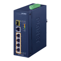
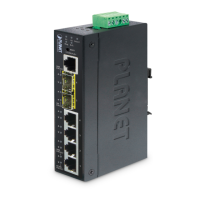
5. Three-View Diagram
The three-view diagram of the Industrial Gigabit Ethernet Switch
consists of multiple auto-sensing 10/100/1000BASE-T RJ45 ports
and one removable terminal block. The LED indicators are also
located on the front panel.
IGS-500T
104.00
30.00
70.00
18.00
9.00
91.00
52.00
52.00
50.00
30.00
21.69
28.65
28.00
48.80
40.00
18.00
40.00
18.00
Mounting Kit
Mounting Kit
DIN-Rail Kit
Unit: mm
Rear ViewSide View Side View
Front View
Bottom View
P1 P2 Fault
1
2
3
4
5
1000
100
IGS-500T
ACTLNK
ACTLNK
Max. fault loading: 24V, 1A
V1+
V2+
PWR1
PWR2Fault
DC Input: 12-48V
, 0.28A max.
AC Input: 24V
, 0.3A max.
Figure 5: IGS-500T Three-View Diagram
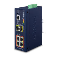
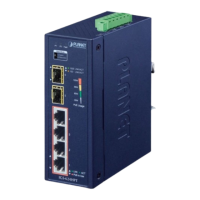
IGS-510TF
104.00
30.00
70.00
18.00
9.00
91.00
52.00
52.00
50.00
30.00
21.69
28.65
30.16
28.00
48.80
40.00
18.00
40.00
18.00
Mounting Kit
Mounting Kit
DIN-Rail Kit
Unit: mm
Rear ViewSide View Side View
Top View
Front View
Bottom View
P1 P2
1
2
3
4
5
1000
10/
100
1000
10/
100
LNK/
ACT
IGS-510TF
ACTLNK
V1+
V1-
PWR1
V2+
V2-
PWR2
DC Input: 9-48V , 0.6A max.
AC Input: 24V , 0.3A max.
Figure 6: IGS-510TF Three-View Diagram
Customer Support
Thank you for purchasing PLANET products. You can browse our
online FAQ resource on PLANET web site rst to check if it could
solve your issue. If you need more support information, please
contact PLANET switch support team.
PLANET online FAQs:
http://www.planet.com.tw/en/support/faq
Switch support team mail address:
support@planet.com.tw
Copyright © PLANET Technology Corp. 2019.
Contents are subject to revision without prior notice.
PLANET is a registered trademark of PLANET Technology Corp.
All other trademarks belong to their respective owners.