- 1 -
- 2 -
- 3 -
- 4 -
- 5 -
- 6 -
- 7 -
- 8 -
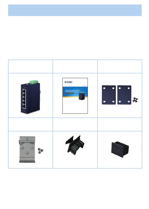
1. Package Contents
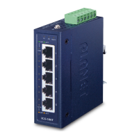
Thank you for purchasing PLANET industrial compact 5-port Gigabit
Ethernet Switch, IGS-500T/IGS-510TF. In the following section, the
term “Industrial Gigabit Ethernet Switch” means the IGS-500T
or IGS-510TF.
Open the box of the Industrial Gigabit Ethernet Switch and carefully
unpack it. The box should contain the following items:
Industrial Gigabit
Ethernet Switch x 1
User’s Manual x 1 Wall-mount Kit x 1
DIN-rail Kit x 1 RJ45 Dust Caps
SFP Dust Cap x 1
(IGS-510TF only)
IGS-500T x 5
IGS-510TF x 4
If any of these are missing or damaged, please contact your dealer
immediately; if possible, retain the carton including the original
packing material, and use them again to repack the product in case
there is a need to return it to us for repair.
Power
Consumption
(Ethernet Full
Loading)
Max. 3.6
watts/12.28BTU
Max. 4.3
watts/14.67BTU
Dimensions
(W x D x H)
30 x 70 x 104 mm
Weight 252g 270g
Enclosure IP30 metal case
Installation DIN-rail kit and wall-mount kit
ESD Protection 6KV
EFT Protection 6KV
Switch Specications
Switch
Architecture
Store-and-Forward
Switch Fabric 10Gbps
Throughput
(packet per
second)
7.4Mpps@64bytes
Address Table 4K entries
Buer Memory 1M bits on-chip buer memory
Jumbo Frame 9Kbytes
Flow Control
Back pressure for half duplex
IEEE 802.3x pause frame for full duplex
V1+
V1-
PWR1
V2+
V2-
PWR2
DC Input: 9-48V , 0.6A max.
AC Input: 24V , 0.3A max.
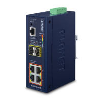
1 2 3 4
Figure 4: IGS-510TF Top View
3.4 Wiring the Power Inputs
The terminal block connector on the top panel of Industrial Gigabit
Ethernet Switch is used for two DC redundant power inputs. Please
follow the steps below to insert the power wire.
Caution
When performing any of the procedures like inserting
the wires or tightening the wire-clamp screws, make
sure the power is OFF to prevent from getting an
electric shock.
[IGS-500T]
1. Insert positive and negative DC power wires into contacts 1 and
2 for POWER 1, or contacts 5 and 6 for POWER 2.
Max. fault loading: 24V, 1A
V1+
V2+
PWR1
PWR2Fault
DC Input: 12-48V
, 0.28A max.
AC Input: 24V
, 0.3A max.
1 2 3 4 5 6
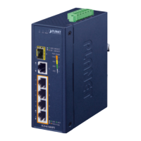
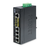
3. Hardware Introduction
3.1 Switch Front Panel
The front Panels of the Industrial Gigabit Ethernet Switches consist
of Ethernet interfaces and LED indicators.
Front View
P1 P2
1
2
3
4
5
1000
10/
100
1000
10/
100
LNK/
ACT
IGS-510TF
ACTLNK
P1 P2 Fault
1
2
3
4
5
1000
100
IGS-500T
ACTLNK
ACTLNK
P1 P2
1
2
3
4
5
1000
10/
100
1000
10/
100
LNK/
ACT
IGS-510TF
ACTLNK
Figure 1:
IGS-500T Front View
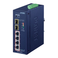
Figure 2:
IGS-510TF Front View
2.ProductSpecications
Model IGS-500T IGS-510TF
Hardware Specications
Copper Ports
5 10/100/1000BASE-T
RJ45 auto-MDI/MDI-X
ports
4 10/100/1000BASE-T
RJ45 auto-MDI/MDI-X
ports
SFP Slot --
1 1000BASE-SX/LX/
BX SFP interface
compatible with
100BASE-FX SFP
Connector
Removable 6-pin
terminal block
Pin 1/2 for Power 1;
Pin 3/4 for fault
alarm;
Pin 5/6 for Power 2
Removable 4-pin
terminal block
Pin 1/2 for Power 1;
Pin 3/4 for Power 2
Alarm
One relay output for
power failure. Alarm
relay current carry
ability: 1A@DC 24V
--
Power
Requirements
12~48V DC,
redundant power
with reverse polarity
protection function,
24V AC power
support
9~48V DC, redundant
power with reverse
polarity protection
function,
24V AC power
support
Standards Conformance
Regulatory
Compliance
FCC Part 15 Class A, CE
Stability Testing
IEC 60068-2-32 (free fall)
IEC 60068-2-27 (shock)
IEC 60068-2-6 (vibration)
Standards
Compliance
IEEE 802.3 Ethernet
IEEE 802.3u Fast Ethernet
IEEE 802.3ab Gigabit Ethernet
IEEE 802.3az Gigabit SX/LX (IGS-510TF only)
IEEE 802.3x Full-Duplex Flow Control
IEEE 802.3az Energy Ecient Ethernet (EEE)
IEEE 802.1p Class of Service
Environment
Temperature
Operating: -40~75 degrees C
Storage: -40~75 degrees C
Humidity
Operating: 5~90% (non-condensing)
Storage: 5~90% (non-condensing)
3.2 LEDDenition:
LED Color Function
P1 Green Lights to indicate power input 1 has power.
P2 Green Lights to indicate power input 2 has power.
Fault Red
Lights to indicate that power 1 or power 2 has
failed. (For IGS-500T only)
1000
LNK/ACT
Green
Lights to indicate the port is running at
1000Mbps speed and successfully established.
Blinks to indicate that the Switch is actively
sending or receiving data over that port.
100
LNK/ACT
Amber
Lights to indicate the port is running
at 10/100Mbps speed and successfully
established.
Blinks to indicate that the Switch is actively
sending or receiving data over that port.
3.3 Switch Upper Panel
The upper panels of the Industrial Gigabit Ethernet Switches consist
of one terminal block connector within two power input.
Max. fault loading: 24V, 1A
V1+
V2+
PWR1
PWR2Fault
DC Input: 12-48V
, 0.28A max.
AC Input: 24V
, 0.3A max.
1 2 3 4 5 6
Figure 3: IGS-500T Top View
2. Tighten the wire-clamp screws for preventing the wires from
loosening.
1 2 3 4 5 6
Power 1 Fault Power 2
+ - + -
[IGS-510TF]
1. Insert positive and negative DC power wires into contacts 1 and
2 for POWER 1, or contacts 3 and 4 for POWER 2.
V1+
V1-
PWR1
V2+
V2-
PWR2
DC Input: 9-48V , 0.6A max.
AC Input: 24V , 0.3A max.
1 2 3 4
2. Tighten the wire-clamp screws for preventing the wires from
loosening.
1 2 3 4
Power 1 Power 2
+ - + -
 Loading...