5
3. Wiring the Power Inputs
The Front Panel of the Managed Metro Switch indicates a DC inlet power
socket and consists of one terminal block connector within 6 contacts. Please
follow the steps below to insert the power wire.
MGSD-10080F Front Panel
1
2
3
4
5
6
7
8
RingPWR
DC 1
R.O.
DC 2
Alarm
ACTLNK
ACTLNK
1G/2.5G
100
Reset
10
9
MGSD-10080F
Console
2
4
6
8
10
ON
AC POWER
DC POWER
ON
OFF
GNDGNDDO 1DO 0DI 1DI 0
V1+ V2+
100-240V
, 0.2A max.
DC Input: 36-60V
,
100/1G 2.5G
CAUTION
Please refer to user’s manual before
connect the DC wire.
Max. Fault Alarm Loading: 24V, 1A
Figure 3-1: MGSD-10080F Switch Front Panel
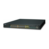
MGS-6320-2T6S2X Front Panel
1
2
3
4
5
6
7
8
RingAC
DC 1 R.O.
Alarm
I/O
DC 2
ACTLNK
ACTLNK
1G/2.5G
100/10G
Reset
10
9
1G 2.5G 10G
CAUTION
Please refer to user’s manual before
connect the DC wire.
GNDGNDDO 1DO 0DI 1DI 0
V1+ V2+
Max. Fault Alarm Loading: 24V, 1A
ON
AC POWER
100-240V
, 1A max.
MGS-6320-2T6S2X
Console
115200,N,8,1
8
6
4
1
2
DC Input
:
10G SFP+
Figure 3-2: MGS-6320-2T6S2X Switch Front Panel
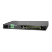
MGSW-28240F Front Panel
ON
AC POWER
DC POWER
ON
OFF
Ring R.O.
FaultFAN2
FAN1
PWR
DC 2
DC 1
DC Input: 36-60V
,
2 4 6 8 10 12 14 16 18 20 22 24 26 28
272625242322212019181716151413121110987654321 28
Console
Reset
115200, N, 8, 1
GNDGNDDO 1DO 0DI 1DI 0
2 4
MGSW-28240F
100-240V , 1A max.100-240V , 1A max.
1G/2.5G
100
10G
1G/2.5G
Figure 3-3: MGSW-28240F Switch Front Panel

 Loading...