INSTALLATION OF THE PLANMECA ETHERNET INTERFACE BOX TO THE DIXI3 DIGITAL INTRA X-RAY SYS-
2 Planmeca Ethernet interface Installation manual
2 INSTALLATION OF THE PLANMECA ETHERNET INTERFACE BOX
TO THE DIXI3 DIGITAL INTRA X-RAY SYSTEM
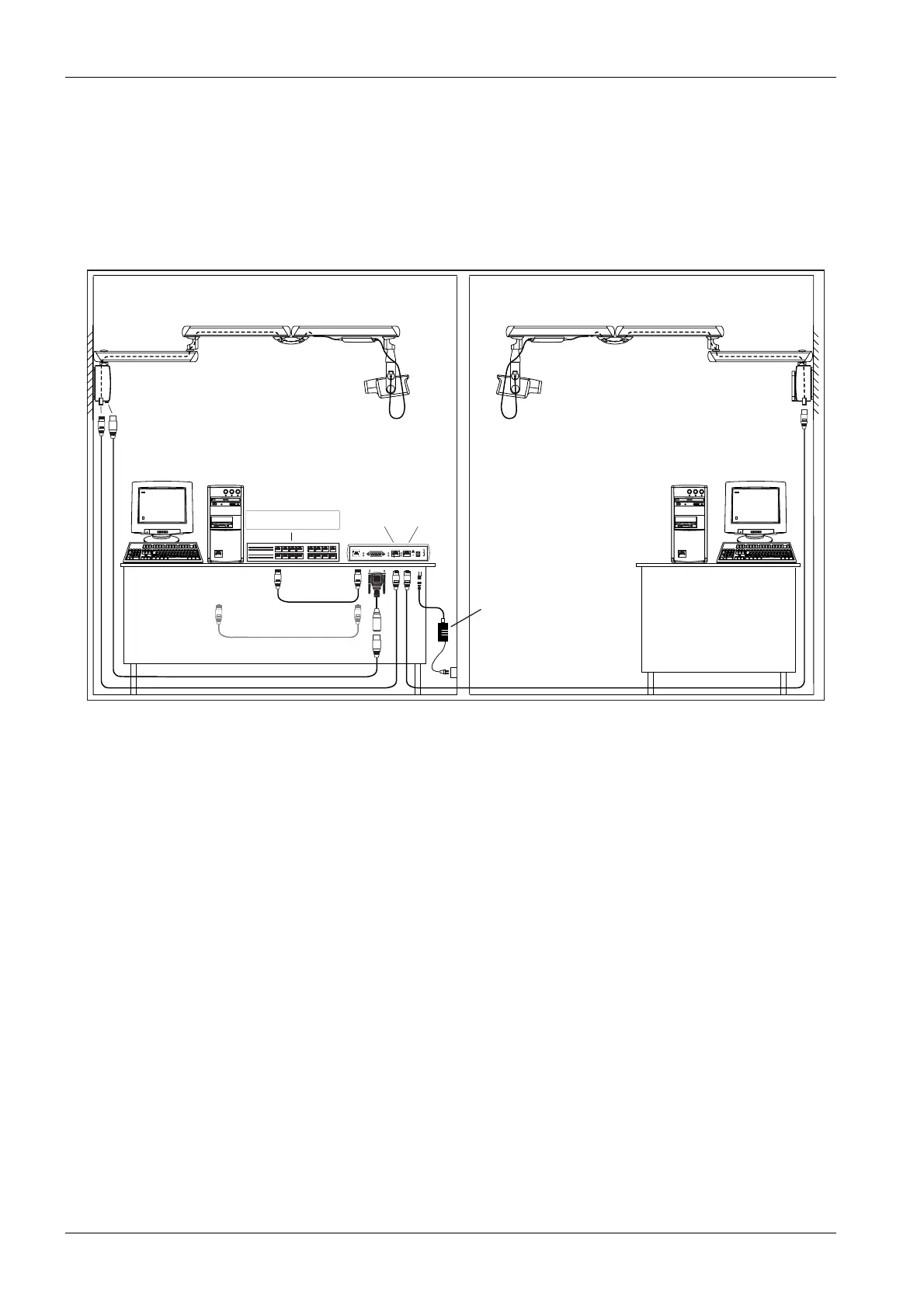
2.1 Overview of the installation
NOTE You can install either two Planmeca Dixi3 digital intra X-ray systems, two Plan-
meca Proline XC systems, or Planmeca Dixi3 digital intra X-ray system and
Planmeca Proline XC X-ray system to the Ethernet Interface.
et_conn_sync.eps
OK
SET
STATUS
TX/RX
LINK
PLANMECA ETHERNET INTERFACE
10/100 Base-T PLANET PORT 2
PWR
PORT 1 13,2VDC IN
max. 1A
PORT1 PORT2
Planmeca Ethernet
Interface
server
Hub / Switch
to Hub / Switch
Cross connected CAT 5 UTP cable
Power Supply:
Mascot type 9920
or
to PC
RJ45
RJ45
CAT 5 UTP RJ45 15m
Intra sync cable
CAT 5 UTP RJ45 15m
PC / Thin client
10/100 Base-T
10/100 Base-T
CAT 5 UTP