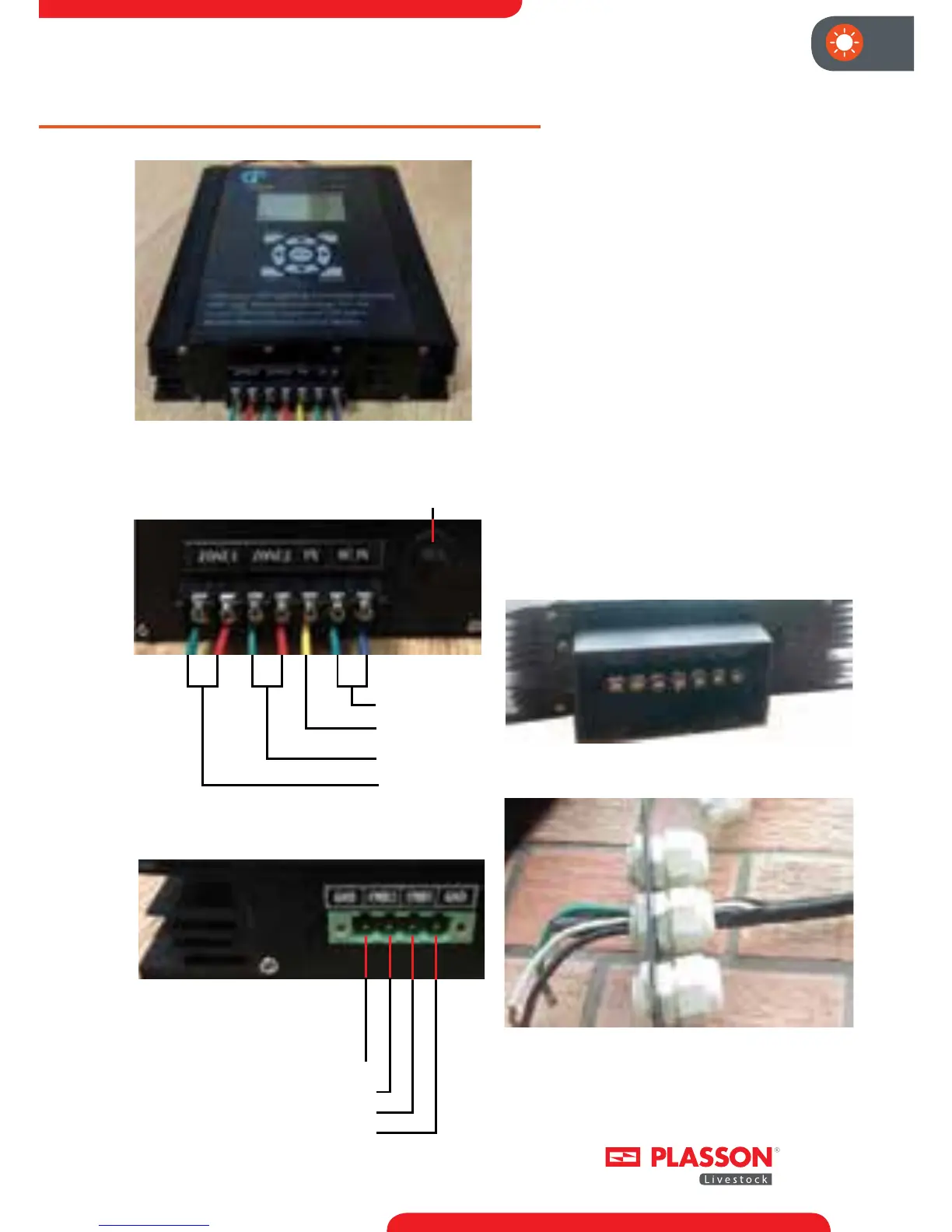
ZONE 2 Analog Command Input -
ZONE 2 Analog Command Input +
ZONE 1 Analog Command Input +
ZONE 1 Analog Command Input -
Before starting to connect the wires
to the dimmer, install the connector
terminal frame over the connectors
with the four screws provided. The
installed frame should look like the
image below in Figure 3a.
ALL Wires which will be connected
to the dimmer should be threaded
through the connecter bladders found
on the terminal frame cover. These
bladders will accept up to a Romex
12-3 cable. Each bladder accepts a
Romex cable for main power (right
side), light line 1 (left Side) and light line
2 (Center). Figure 3b below shows the
light line 2 ROMEX threaded through
the center frame cover bladder.
Fig. 1: The Plasson Dimmer-Controller
AC Input
Earth GND
Zone 1 Output
Zone 2 Output
z + z + z +
Overload Protector
Fig. 2: The connection of AC Power lines.
Fig. 3: Connection of slave
analog command voltage.
Fig. 3a: Connector frame
Fig. 3b: Connector frame cover with bladders