6 | Dimmer User Manual
Note: Now it is time to connect the wires. Remember that the center Romex/
wire connects to Light Line 2 (shown in Figure 3c. on right, The right Romex/wire
connects to power and the left Romex/
wire connects to Light Line 1. It is critical
that you connect the positive and neutral
wires to the same terminal connections
for the AC in Zone 1 and Zone 2. The
left terminal connection is ALWAYS the
neutral connection and the right terminal
connection is ALWAYS the positive
connection. DO NOT MIX THESE UP WHEN
CONNECTING THE DIMMER!
START BY CONNECTING THE GROUND
WIRE!
Connections are shown in Figure 2.
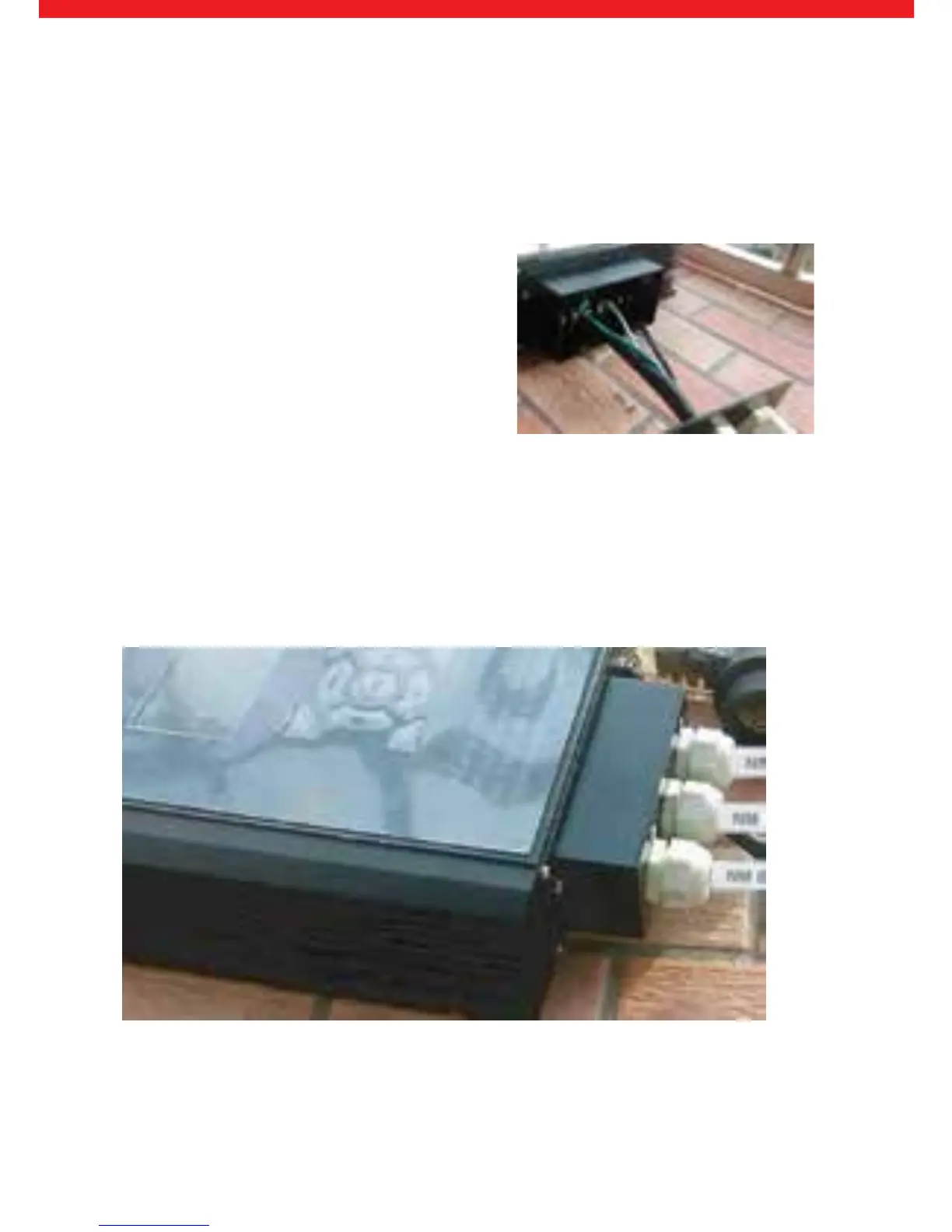
After all the wires are connected to the dimmer, now slide the connector fame cover
and bladder assembly over the connection terminal frame and screw the cover into
place. At this time all of the wires will be coming out of the bottom of the dimmer
as shown below in Figure 3d.
Figure 3d: Final connected dimmer