Connect Water Supply
CAUTION: All plumbing installations must comply with
local building and safety codes, and must be performed by
qualified personnel only.
NOTE: Coolers should not be connected to “soft” water systems. Soft
water will accelerate corrosion and decrease the effective life of the
pad and the cooler cabinet. Connect water line as follows:
A water supply valve should be installed at a convenient location,
to allow the water supply to be turned on and off for servicing or
winterizing. Minimum 1/4“ diameter tubing should be used to
provide water to the cooler, larger tubing is recommended if the
distance from the valve to the cooler is greater than 100 feet, then
reduced to 1/4” at the unit.
Install float valve in the cabinet as shown in Figure 3.
Connect tubing from water supply to float valve. Place
compression nut and ferrule over end of tubing, insert tube into
float valve then tighten compression nut to secure.
Turn on water supply and check for leaks. Adjust float to maintain
the water level at 2” to 2 ½”.
Install Bleed-off (Model WH2906)
To minimize mineral scale “build-up”,
use the included bleed-off assembly.
Remove the cap from the bleed-off tee;
insert the 1/4” diameter black tubing
and route the tubing through the 7/16”
hole in the side of the cooler opposite of
the float valve. Run bleed-off tubing to a
proper drain To prevent siphoning of
the water, make sure t at the bleed-off
tee is above the water level.
NOTE: Drain water in accordance with local plumbing codes.
Install fitting for drain pump (HE2913)
To minimize mineral scale “build-up”, these window cooler models
include an automatically timed drain pump for removing mineral laden
water from the cooler pan. It is factory set to operate every 8 hours of
unit operation in the “COOL” mode and will run for 5 minutes. Install
the drain bushing for the auto-dump drain pump discharge hose in the
side of the cooler as follows: (See figure 4)
Locate drain hose assembly in bottom of cooler and remove lock
nut from drain bushing (leave rubber washer in place). Check that
the opposite end of the hose is still connected to the drain pump.
Push drain bushing through hole in side of cooler (opposite of float
valve), rotate hose until anti-siphon fitting tube is pointing toward
bottom of cooler, then assemble and tighten lock nut.
Connect a suitable drain line (garden hose, etc) to the drain
bushing. Never drain water onto a sidewalk or other hard surfaced
area; mineral build-up or a slipping hazard may occur.
.
h
Fig 4
Evaporative Window Cooler - Use and Care Manual 3
GENERAL INSPECTION
Initial Start-up or Annual Inspection
CAUTION: Disconnect all electrical power to the cooler
before attempting to install, open, or service your cooler.
Before start-up of the cooler for the first time, or at the beginning of
each cooling season, make sure that all required connections,
adjustments, etc. have been made. Verify that:
P Cooler mounting is level; window duct is sealed.
P Power supply cord is correctly routed, safe and secure.
P Bleed-off / drain pump is correctly installed and fully functional.
P Water line securely connected, turned on, no leaks noted.
P Float valve is correctly installed, adjusted for proper water level
and fully operational.
P Pump impeller turns free and smooth. If in doubt, remove
impeller cover (see “Cleaning Pump”).
P Blower wheel turns freely.
Start-up Check List
CAUTION: Never operate cooler with pad frame(s) or air
outlet grille removed. This will result in an overloaded
condition and may damage the blower motor.
To verify and check out the cooler installation on initial or annual start-
up, the following procedure should be followed.
P Open building exhaust / relief vents (windows, doors, etc.)
P Plug supply cord into receptacle. Switch “COOL” to “ON”.
P Verify that the pump starts and pad evenly wets.
P Switch “FAN” to “HIGH”, observe that motor starts and runs.
P Switch to “LOW”, observe that motor changes to low speed.
In case of trouble on any of these steps, refer to the Troubleshooting
Chart on
Cabinet Inspection Checklist
After initial start-up and for a few weeks afterwards, check for and/or
observe the following: Refer to the Troubleshooting Chart on f
necessary.
P Leaks from water lines, pad frame, cabinet, etc.
P Cooler pad: even wetting, no dry streaks.
P Confirm water level depth setting is correct.
P Verify full, even flow in water distribution system.
P Blower wheel rotates freely, no unusual noises.
P Check motor mounting, cabinet hardware, setscrews on blower
wheel are tight.
page 6.
page 6 i
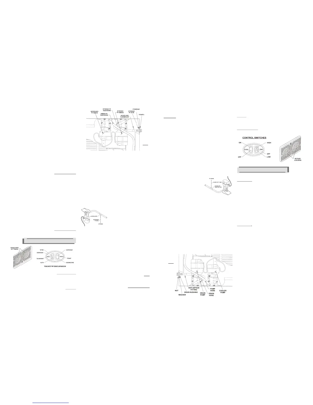
Cooler Operation
Controls:
The rocker control switches are used to select the operating mode
of the window cooler. These switches control fan speed (HI / OFF /
LOW) and the cooling operation (ON / OFF).
Grille airflow control:
Rotate each louver ring until desired air flow direction is reached.
Enfriador Evaporativo de Ventana - Maunal de Uso y Cuidado 3
INSPECCIÓN GENERAL
Lista de inspección de pre-comienzo o anual
PRECAUCION: Desconecte toda la corriente eléctrica
del enfriador antes de intentar instalar, abrir, o darle
servicio a su enfriador.
Antes de prender el enfriador por primera vez, o en el comienzo de
cada temporada de enfriamiento, asegúrese de haber hecho todas
las conexiones y ajustes. Verifique que:
P Montura del enfriador a nivel; ductos de ventana sellados.
P El cordón clavija este correctamente guiado, seguros y
fuera de peligro.
P Sangrado o bomba de purga están correctamente
instaladas y funcionales.
P Línea de agua seguramente conectada, abierta, sin fugas
notables.
P Válvula del flotador están correctamente instaladas y
funcionales, ajustado al propio nivel.
P Impelente de la bomba gira libre y suave. Si hay duda
remueva la cubierta del impelente (véase “limpieza de la
bomba”) y revise la rotación.
P Turbina gira libremente.
Chequeo de empiezo
PRECAUCION: Nunca opere la unidad sin el filtro o
rejilla del aire. Esto resultaría en condición de sobrecarga
y podría dañar el motor de la turbina.
Para verificar y chequeo de la instalación del enfriador en el comienzo
inicial o anual, siga el siguiente procedimiento.
P Habrá las salidas / ventilaciones (ventanas, puertas, etc.)
P Enchufe el cordón clavija en el receptáculo de pared.
P Verifique si la bomba empezó y los filtros se mojan parejos.
P Observe comienza y funciona.
En caso de problemas en alguno de estos pasos, refiérase a la lista
de trazando fallas en página 6.
Lista de inspección del gabinete
Después del comienzo inicial y durante inspecciones periódicas,
revise u observe lo siguiente: Refiérase a la lista trazando fallas en la
página 6 si es que es necesario.
P Fugas de las líneas de agua, filtro, gabinete, etc.
P Filtro de enfriador: se mojen parejos, no áreas secas.
P El ajuste del nivel del agua sea correcto.
P Verifique el flujo de agua completo y parejo en el
sistema de distribución.
P Turbina / motor giran libremente, no ruidos extraños.
P Revise la montadura del motor, tornillos del gabinete, tornillos
opresores de la turbina apretados.
Operación de Enfriador
Controles:
Los interruptores se utilizan para seleccionar el modo de operación
del enfriador de ventana. Estos interruptores controlan la velocidad
de la turbina (ALTA / APAGADO / BAJA) y la operación de
enfriamiento (ENCENDIDO / APAGADO).
Parrillas giratorias:
Gire cada parrilla hasta alcanzar la dirección de aire deseada.
Conecte el Suministro de Agua
PRECAUCION: Todas las instalaciones de plomería
tienen que cumplir con los códigos de edificar y reglas de
seguridad, y llevadas a cabo por personal competente
solamente.
NOTA: Los enfriadores no se deben conectar a sistemas de agua
“blanda”. Agua blanda acelera la corrosión y reduce la vida efectiva de
los filtros y gabinete. Conecte el suministro de agua como sigue:
La válvula de suministro de agua podría instalarse en un sitio
conveniente, para permitir abrir y cerrar para dar servicio o
apagado de invierno. Un tubo con un mínimo de 1/4” se debe usar
para el suministro de agua hacia el enfriador, Un tubo más grande
se debe usar si la distancia es mayor de 100 pies y reducida a 1/4”
en la entrada de la unidad.
Instale la válvula del flotador en el gabinete como se indica (fig. 3)
Conecte un tubo del suministro de agua al flotador. Ponga la tuerca
de compresión y la férula sobre el extremo del tubo, inserte el tubo
en la válvula y apriételo la tuerca de compresión bien.
Abra el suministro de agua y revise si hay fugas. Ajuste el flotador
para mantener un nivel de 2” a 2 ½..
Instale el sangrado (Model WH2906)
Para minimizar la “acumulación de sarro’,
use la sangría incluida. Remueva el tapón
del adaptador “T” e inserte tubo negro y
guíelo a través del agujero de 7/16’ en el
costado opuesto a la válvula del flotador.
Recorra el tubo de sangrado hacia un
grenaje apropiado. Para prevenir sifónaje
del agua, asegure que la “T” del sangrado
esté arriba del nivel del agua.
NOTA: Drene el agua de acuerdo con los códigos locales de plomería.
Instale el aditamento para la bomba de drenaje (HE2913)
Para minimizar la "acumulación de sarro", en el modelo HE2912 enfriador
de ventana se incluye una bomba con temporizador para remover el agua
cargada de minerales del depósito. Ajustado en la fábrica para operar
cada 3 horas por 6 minutos en la operación de "COOL". Instale el buje de
drenaje para la manguera del sistema automático de drenaje en el
costado del enfriador como sigue: (ver figura 4)
Coloque el ensamble de la manguera removiendo la tuerca del buje
(dejando la arandela de hule en su lugar). Revise si el lado opuesto de
la manguera aún esté conectada a la bomba de drenaje.
Inserte el buje de drenaje através del agujero en el costado del enfriador
(lado opuesto a la vávula), girar la manguera hasta que el aditamento
anti-sifón apunte hacia el fondo del enfriador, atornille la tuerca.
Conecte una linea adecuada de drenaje (manguera de jardín, etc) al
buje de drenaje. Nunca drene el agua en la banqueta u otra area con
superficie dura: ya que con la acumulación de sarro se puede poner
resbalosa.
Fig 4


 To Next Page
 Loading...
