EasyManua.ls Logo

POLA HP31 User Manual

Default Icon
2 pages
To Next Page IconTo Next Page
Page #1 background imageLoading...
Page #1 background image
HP31
Handbook
SL 3.0
Luminosity Controller
LUMINOSITY SETTING.
Press LUMIN (key lamp flashes):
This message will be displayed instead of the
Luminosity value (K.Lux).
Press + or - to modify. Press LUMIN to confirm.
MAIN SETTINGS (Run Mode)
Example with L.SEt = 50.0L
Attention: the reading of luminosity probe is only indicative.
Verify only with one precision luxometer the real reading of correspondence.
INSTALLATION
How to connect the line
Connect line on terminals L-N.
Protect supply with adequate fuse.
How to connect the contacts
Connect terminals on the terminal block (contacts up to 4AMP.AC1).
How to connect the sensor
Connect the provided sensor as shown in the diagram.
For remote connections use a standard 0.5-square millimeter two-pole wire , taking
great care over the connections, by insulating and sealing the joins carefully.
HP31
* Other power voltage if you required
230V LINE *
SHIELD CLOSING
LX LUMINOSITY
SENSOR
SHIELD OPENING
DAILY TIMER
N.O. CONTACT.
As it company policy to continually improve the products the Manufacturers
reserve the right to make any modifications thereto without prior notice. They
cannot be held liable for any damage due to malfunction.
21.12.12
Question and Answer IconNeed help?

Do you have a question about the POLA HP31 and is the answer not in the manual?

POLA HP31 Specifications

General IconGeneral
BrandPOLA
ModelHP31
CategoryController
LanguageEnglish

Summary

Installation and Connections

Sensor and Line Connection

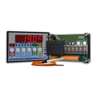
Connect the sensor and line to L-N terminals using a two-pole wire, ensuring proper insulation and fuse protection.

Contact Wiring

Connect terminals on the block for contacts rated up to 4AMP.AC1, ensuring secure connections.

Main Settings and Operation

Luminosity Setting Adjustment

Modify the luminosity setpoint using +/- keys; press LUMIN to confirm the value displayed.

Operational Modes and Data Viewing

Manual Mode Operation

Activate manual mode by pressing '+' during power-on for direct relay control and operation.

Viewing Temperature Records

Access and clear stored maximum and minimum ambient temperature recordings from the device memory.

System Configuration and Presets

Cost Programming

Configure system constants like neutral range, modulation bands, and on/off times for operation.

Preset Programs (Bootstrap)

Restore factory default settings by holding the LUMIN key during power-on.

Status Indicators and Diagrams

State Indication Lamps

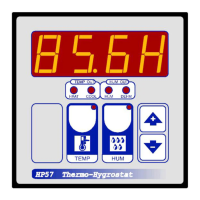
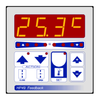
Interpret the meaning of the indicator lamps on the display for relay status and action.

Operative Diagram Explanation

Understand the functional logic, timing, and switching operations through the provided diagram.

Related product manuals