HP57
Handbook
SL 3.1
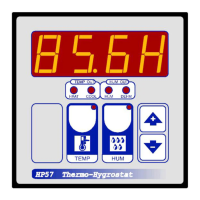
Thermo-Hygrostat controller
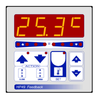
Example with SEt.t = 20.0°
Example with SEt.H = 80.0H
TEMPERATURE SETTING.
Press TEMP key (key lamp flashes):
This message will be displayed instead of the
°C Set Temperature value.
Press + or - to modify. Press TEMP to confirm.
HUMIDITY SETTING.
Press HUM key (key lamp flashes):
This message will be displayed instead of the
% Rh Humidity value.
Press + or - to modify. Press HUM to confirm.
MAIN SETTINGS
VIEWING AMBIENT TEMPERATURE AND AMBIENT HUMIDITY RECORDING
Values recorder are memory permanent stored: for memory clear keep pushed + keys for more than
3 seconds: CLEA message will be composed on display before clearing operation.
Press - : will be displayed followed by
°Minimum Temperature Recording.
Press + : will be displayed followed by
°Maximum Temperature Recording.
TEMPERATURE RECORDING VIEWING.
Press TEMP key and after:
Press - : will be displayed followed by
°Minimum Humidity Recording.
Press + : will be displayed followed by
°Maximum Humidity Recording.
HUMIDITY RECORDING VIEWING.
Press HUM key and after:
VIEWING TEMPERATURE AND HUMIDITY
With TEMP key lamp light (press TEMP key) ambient temperature is
displayed. With HUM key lamp light (press HUM) ambient humidity is
displayed (if the humidity is obtained with "wet bulb" pressing HUM for
more than 3 second on display will appear the message t.vEt in turn of
obtained value of temperature probe "wet bulb").
How to connect the sensors
To connect the 2 probes use N.2 two- wire
cable 0,5 mm2 section, taking great care over
the connections, by insulating and sealing the
joins carefully. -O.C.- is displayed when the
temperature sensor wiring is open, -S.C.- is
displayed when the temperature sensor wiring
is short circuit.
How to connect the contacts
Connect terminals on the terminal block
(contacts up to 4AMP.AC1).
How to connect the line
Connect line on terminals L-N.
Protect supply with adequate fuse.
INSTALLATION
*1 Other power voltage if you required.
COOL OUTPUT
HP57
HEAT OUTPUT
HUMIDITY
PROBE *2
TEMPERATURE
PROBE SX
DEHUM OUTPUT
HUM OUTPUT
230V Line *1
As it company policy to continually improve the products the Manufacturers
reserve the right to make any modifications thereto without prior notice. They
cannot be held liable for any damage due to malfunction.
08.01.13
*2 How to connect 4-20mA electronic humidity probe.
Huny=1 electronic humidity probe
connection.
11 12
-
+
+
-
Probe
4-20mA
HALI
power pack
R
R= 100 ohm resistor to be shunted.
WT1 Option.
Psichrometric kit with predisposition to fixing
ambient probe (SX air) and wet probe (SXPS
water). Water tank with trasparent side to
check the water level and plug for water inlet.
In the case of our WT1 option (water tank) will not
used, deep only the terminal side of the wetting
cover of SXPS probe.
Put SX probe (dry bulb) in the closeness.
*2 How to connect humidity-psychrometer system (wet bulb).
Check periodically the sock installed on the sensor has not been clogged by calcium carbonate
scale. If so, remove it then clean or replace it.
Wetting cover.
Water-container
(not our forniture).
SXPS: temperature probe
for wet bulb.
11 12
11 12
9 10