EasyManua.ls Logo

POLA HP49 User Manual

POLA HP49
2 pages
To Next Page IconTo Next Page
Page #1 background imageLoading...
Page #1 background image
INSTALLATION
How to connect the ventilation input
Connect the ventilation input provided as shown in the diagram.
How to connect response potentiometer :
Connect the response potentiometer of each value (max 10.000 ohm,
recommended 1 Kohm type) and connect the terminals 7-8.
For remote connections use a standard 0.5-square millimetre two-poles wire for
each sensor, taking great care over the connections, by insulating and sealing
the joins carefully.
How to connect the contacts
Connect terminals on the terminal block (contacts up to 4AMP.AC1) to the loads
as shown in the diagram).
How to connect the line
Connect line on terminals L-N.
HP49
Handbook
Associative flap with feedback
SL 6.0
* Other power voltage if you required.
230 V LINE*
Closed
Open
Common
Flap
command
Flap potentiometer
max 10 Kohm
*1
R
R
R
R
R
R
C1 C2 C3 C4 C5 C6
R= 100 ohm resistor
C1= Ventilation 1 contact
C2= Ventilation 2 contact
C3= Ventilation 3 contact
C4= Ventilation 4 contact
C5= Ventilation 5 contact
C6= Ventilation 6 contact
*1
Recommended 1 Kohm type.
HP49
As it company policy to continually improve the products the Manufacturers
reserve the right to make any modifications thereto without prior notice. They
cannot be held liable for any damage due to malfunction.
19.07.06
Question and Answer IconNeed help?

Do you have a question about the POLA HP49 and is the answer not in the manual?

POLA HP49 Specifications

General IconGeneral
BrandPOLA
ModelHP49
CategoryController
LanguageEnglish

Summary

Installation Guide

Connect Ventilation Input

Connect the ventilation input as shown in the diagram.

Connect Response Potentiometer

Connect potentiometer (max 10k ohm) to terminals 7-8 using a two-pole wire.

Connect Line Input

Connect the power line to terminals L-N.

Connect Load Contacts

Connect terminals to loads (up to 4AMP AC1) as shown in the diagram.

Operating Modes

Run Mode Display

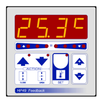
In normal operation, the display shows the percentage of flap position.

Flap Potentiometer Initialization

Procedure to record potentiometer values for the flap motor.

Preset Programs and Hand Mode

Details on pre-programmed settings and manual relay control during start-up.

System Configuration

COSI Programming (System Constants)

Settings for system operation, configured during initial start-up.

State Indication Lamps

These lamps indicate the status of the ventilation input signal.

Related product manuals