-
-
th~
spring
whm
the movable line merges
adjustment
1,.'
..
0 also he "lill.1i: hy turning
thL'
with the
fix~d
.line.
eccentric which l,:onlrols the hcight
of
the
magnec
4.
Paranax Horizontal Adjustment for
d.
Position the cover
plate
on
lilc RF,iVF
and
Zeiss
Ikon RF/VF
secure
it
with
its:
rel",ining screws.
PI
...
ce
th~
-
u.
Remove the two cover retaining screws and
cover back
on
the
RF/VF
and replace the
lift
the cover
off
the RF/VF assembly.
Re~
two retaining screws.
-
move
the
retaininJ
screWs
and remove the
l:over olate.
S.
PIIraJlax
Vertical Adjustment for Zeiss
Ikon
-
I>.
aarnp
the camera onto the
collimator
as
explained in Section In
and
aim
the
camera
at the frame target.
••
Remove
the
two
cover
retaining screws
and
lift the cover
off
the
RF/VF
a5.~embly.
Rc-
move
the
two
screws
whjch
hold
the
cover
plate and take the cover plate
off
the
<.
Observe
the
frame target
through
the
RFfYF
RF!VF.
-
-
eye lens. Using ajeweJer's screwdriver, turn
the
horizontal
adjusting screw
until
the
top
horizontal line
of
the yellow
projected
frame
image is within the area
bounded
by
the
180
close--up target lines when the focus
bar
is
set
b.
c.
Clamp
the
camera
onto
the collimator
as
explained
in
Seettan
til
and aim
the
camera
at
the frame target.
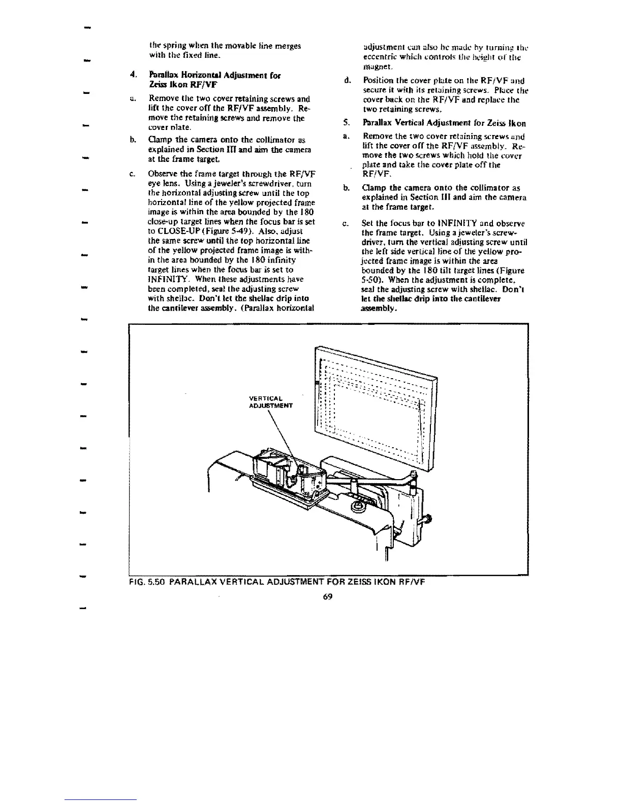
Set the focus bar
to
INFINITY
and
observe
to CLOSE-UP (Figure
549).
Also, adjust
the frame target. Using a jeweler's
screw~
the same screw until
the
top
horizontal1ine
driver,
tum
the verticaJ adjusting screw until
-
of
the
yeUow projected frame image
is
with-
the left side verticaJ line
of
the yeUow
pro-
in
the
area bounded
by
the
180
infinity
jeeted
frame image is wHhin the area
target lines when the
fOC\ls
bar is set
to
bounded
by
the
180
tilt target Jines
(Figure
-
INFINITY. When these
adjustments
have
been
completed.
seat Ihe adjusting screw
5~50).
When
the
adjustment
is
complete.
seal
the
adjusting screw wIth shellac.
Don't
with shellac.
Don't
let
the
shellac
drip
into
let
the shellac
drip
into
the
cantilever
the cantilever assembly. (Parallax horizontal
assembly.
-
-
-
-
-
-
-
-
VERTICAL
ADJUSTMENT
<:
..
":
\.
' ..
:.
FIG.
5.50
PARALLAX VERTtCAL ADJUSTMENT FOR ZEISS IKON
RFNF
69
 Loading...