--
d. Posilion
'h~~
t.·OVl'( plate
Ott
the
RF/VF
and
~'Cl,lre
il
with its two retaining screws. Place
the cover back
O~l
the
RF/VF
and
secure
ir
with
the
two retaining
!?crews.
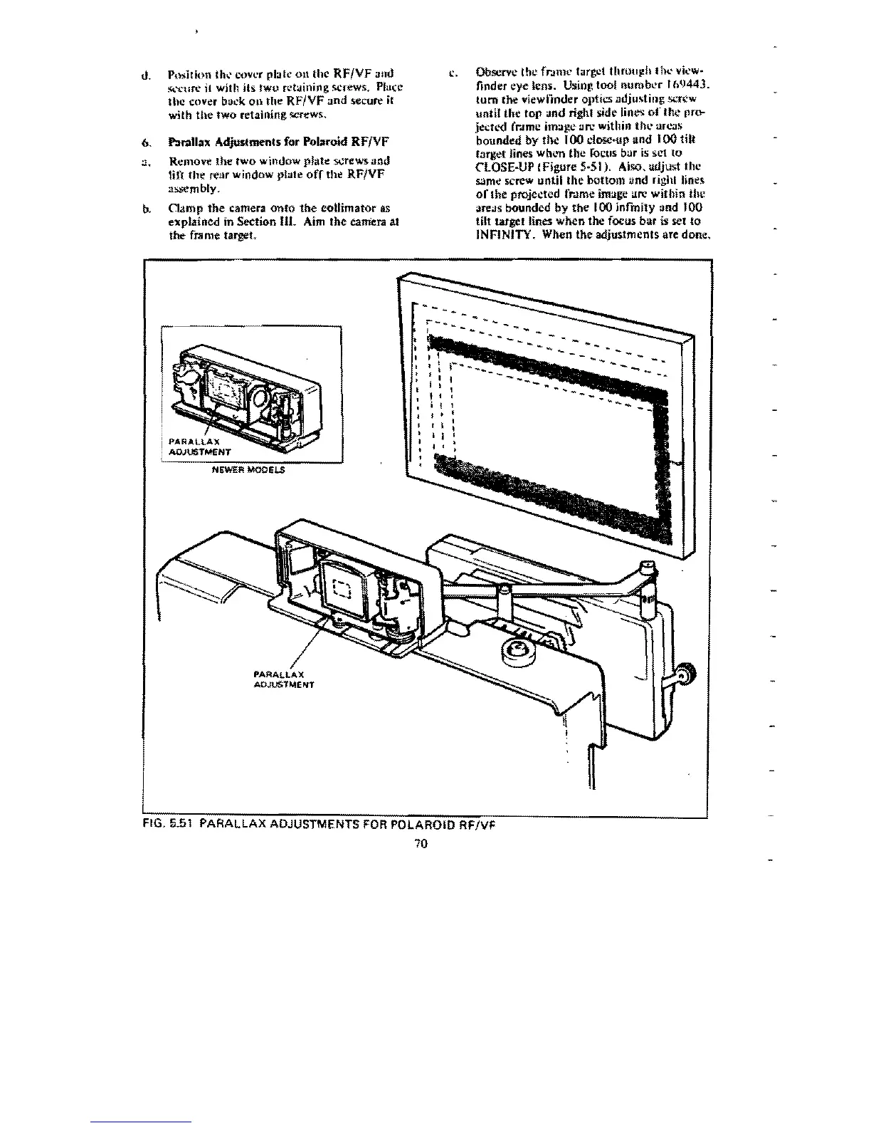
6.
Par.lllax Adju:stments for Polaroid
RF/YF
:.1.
Remove the two window plate screws und
tHi
the
rear window plate
off
the
RF/VF
J!~mbly.
b.
Clamp
the
camera
onto
the
eoUimator
as
explained in Section ttl.
Aim
the eamera at
the
fra
me
target.
t.:.
Observe the frJ1llc target
thruu~h
till'
vil'w~
finder eye .ens. Using tool numb.:r
'69443.
tum
tbe viewfinder optics adjusting
.screw
until the top and right side lines
of
the
pro-
jedl.'d (r.!me image arc within
thc
areas
bounded
by
the'
00
close-up and 100 tilt
target
lines
whl.'Tl
the
JOCtlS
bar
is
st.'1
to
nOSE-UP
(Figure
5-51
J.
Also. adju.! the
same screw until the bottom and right lines
or
the projected fr.Jme image arc within the
i.lTei.lS bounded
by
the
100
infmity and 100
tilt target lines
when
the focus bar is set to
INFINJTY. When the adjustments are done.
PARALLAX
AOJUSTME"NT
NEWER MODELS
PARALLAX
ADJUSTMENT
"
-"
'-
FIG.
5.51
PARALLAX ADJUSTMENTS
FOR
POLAROID
RFNF
70
r_
..
_
-',
 Loading...