REAR AV Connections
INSTALLATION
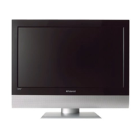
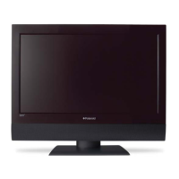
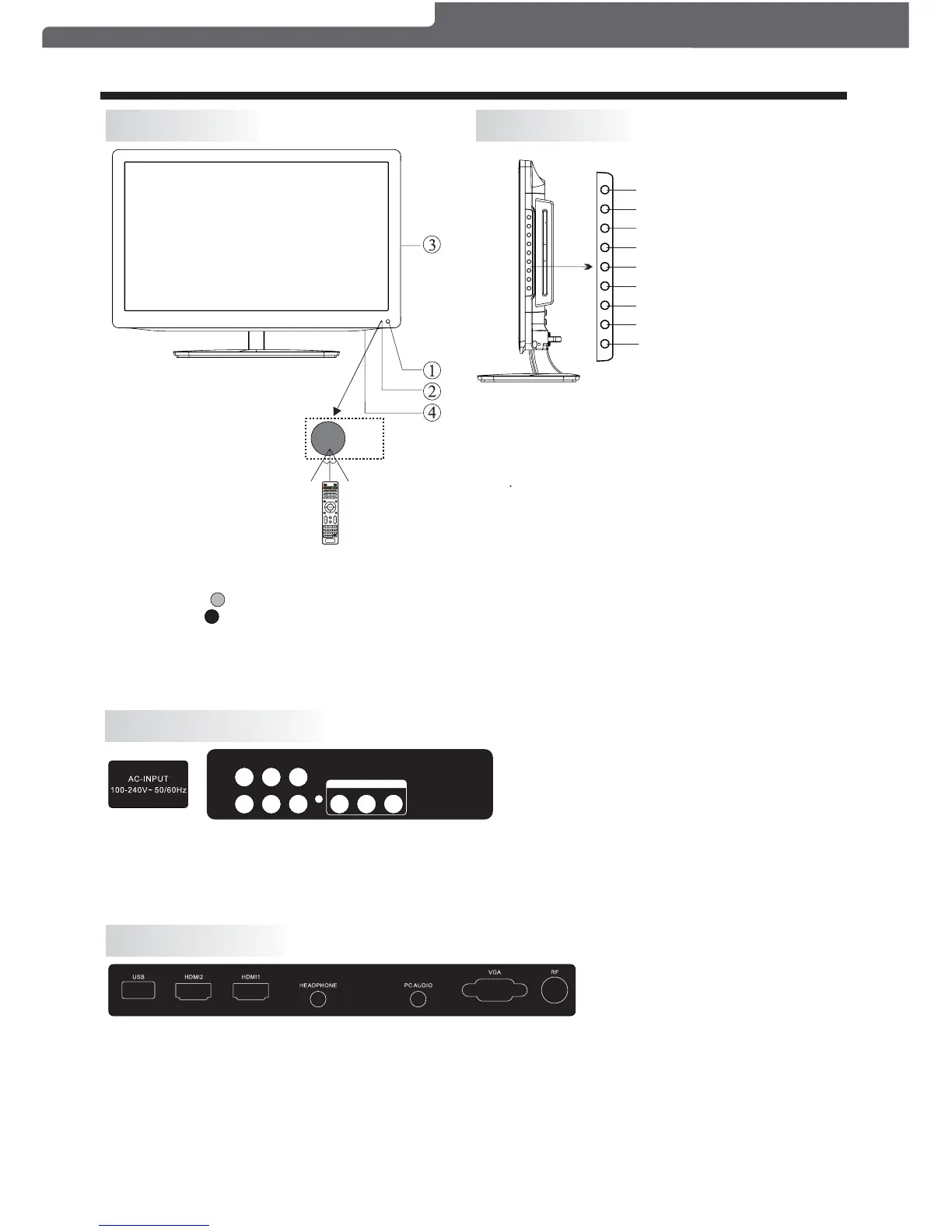
Front Panel
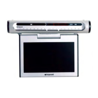
Side Control Panel
1: Remote control sensor.
2: Indicator LED:
BLUE = POWER ON.
RED = Stand-by.
3: Keypad (on side panel of TV).
4: Main power switch (on bottom
panel ofTV)
30 30
Terminal Lay-out is below (from left to right) :
YPbPr (component video) inputs, L+R Audio inputs,
, (composite video and L+R audio).
2. The AV output sockets are only functional when an external device is plugged in.
AC Power Input, AV composite video
input AV output
SIDE AV Connections
Terminal Lay-out is below (from left to right):
USB, HDMI2 input, HDMI1 input, HEADPHONE output, PC Audio input, VGA input,
by the PC Audio input.
2. When the HDMI2 port receives a DVI signal, the matching audio signal is received
by the YPbPr/AV Audio input.
Antenna socket.
YPbPr
RL
VIDEO
R
L
VIDEO
AV OUT PU T
1. VIDEO and YPbPr share the same L+R audio inputs.
NOTE:
1. When the HDMI1 input receives a DVI signal, the matching audio signal is received
NOTE:
1.
2. PLAY/PAUSE
PLAY or PAUSE playback.
3.SOURCE:
Displays the input source Menu.
4.MENU:
Displays the main MENU.
5.CH+/CH-
In TV mode, press "CH+" or "CH-" to change the
channel up or down.
In MENU mode, press "CH+" or "CH-" to select items.
6.VOL+/VOL-
Adjusts the sound level.
In MENU mode, press "VOL+" or "VOL-" to adjust the
item that you have selected.
7. STANDBY
Once the TV's main power switch has been activated,
press this button to turn the unit ON from STANDBY mode.
Press it again to return the set back to STANDBY.
SOURCE (Input selection)
MENU
CH+
CH-
VOL+
VOL-
STANDBY (Power ON/Stand-by select)
PLAY/PAUSE
Polaroid • I0312/I0313
-6-
EJECT
EJECT
To eject the disc from the disc tray
 Loading...