Page 38
I
I
I
Remove the sparkplug (careful, it will still be hot!) and closely examine
the insulator of the plug. The insulator is the ceramic portion of the plug just
behind the metal tip in the center of the plug. If the insulator is white and
appears glazed, the bike is probably too lean. Try a richer main jet and retest.
If the insulator is a light brown or medium grey color, the jetting is proba-
bly just right. If the insulator is dark colored and oily, the main jet is proba-
bly too rich. Decrease the main jet by one size and retest. Always make sure
to retest when installing a leaner main jet to avoid jetting too lean and dam-
aging the motor.
Ignition timing - To check the ignition timing, a dial indicator will be
required to measure piston travel. A special unit is made specifically for this
purpose and can be purchased from Action Racing. Any indicator will work
if it will fit and can be secured for testing. To check timing, remove the alter-
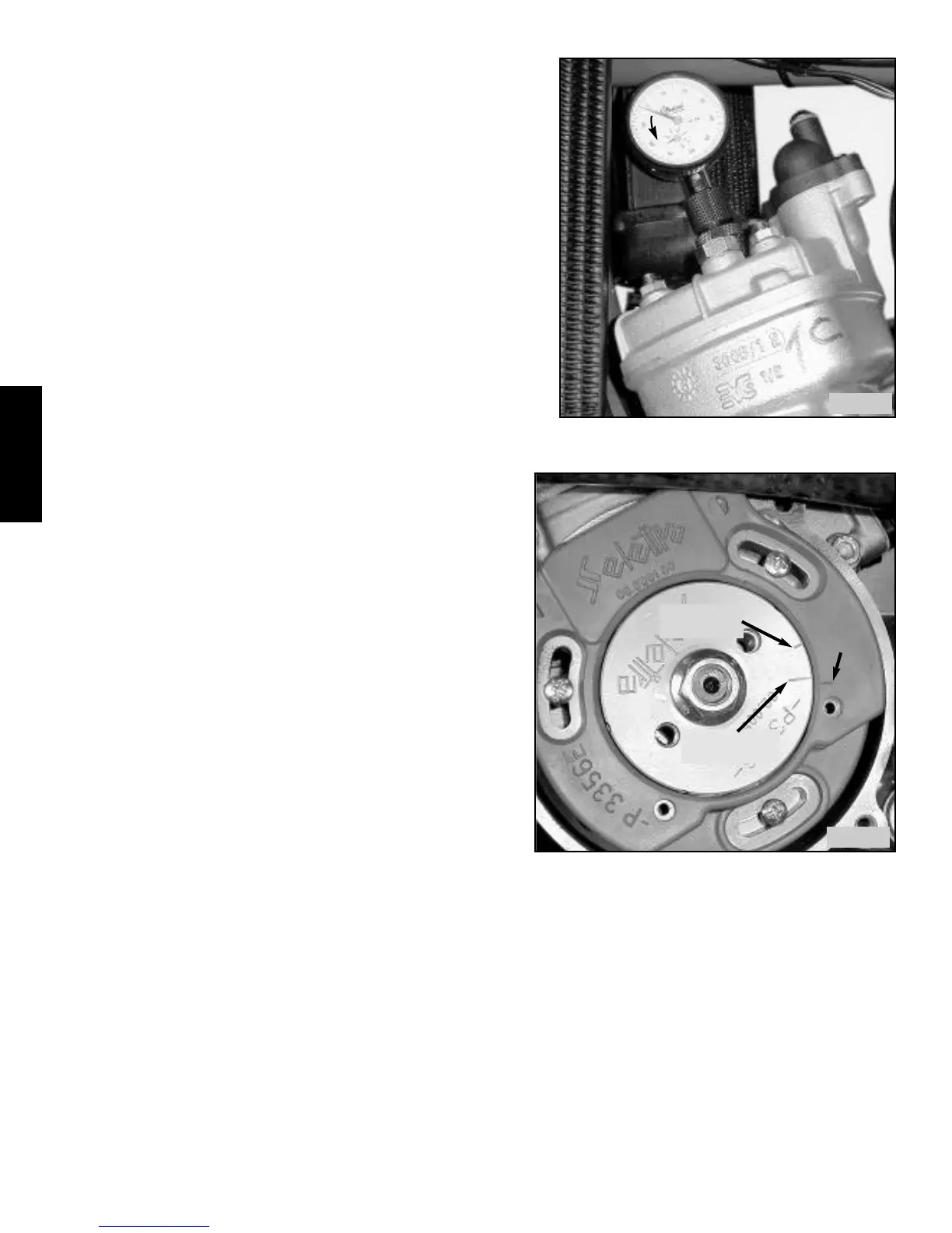
nator cover, seat and fuel tank. Note the two marks on the flywheel and the
mark on the stator assembly. The short mark on the flywheel is where the
ignition is supposed to fire when it lines up with the mark on the stator. The
long mark is roughly top dead center (TDC) when it lines up with the mark
on the stator. See photo III.69.
Next, remove the sparkplug and insert the dial indicator. It is a tight fit on
the X1, you have to push the gage all the way into the adapter, insert the
assembly. into the head, then hold the gage and turn the adapter into the
head until tight, then tighten the locking nut to secure the gage.
Find top dead center (where the piston stops moving up, and starts
going down again). Make sure you don't jam the gage with the piston,
proceed slowly and adjust gage as needed. Turn face of gage so it reads 0
at TDC. See photo III.68. Turn flywheel slowly using 15mm wrench on
the nut until the short mark lines up with the mark on the stator. When the
marks line up, you should indicate 1.6mm of piston travel (.063˝) Be care-
ful when checking the travel, as the dial indicator reads backwards, i.e. if
your indicator reads in mm, you should go 1 complete revolution (1mm),
then to 40, which is .60mm traveled counterclockwise. If the marks don't
line up, recheck, making sure your 0 measurement is still correct. If so,
loosen the 3 screws holding the stator, and holding the flywheel in posi-
tion rotate the stator until the two marks line up (with the piston at
1.6mm) Then tighten the screws. Recheck the 0 measurement and the fir-
ing measurement and make any final adjustments. Check to make sure the
flywheel doesn't rub the stator, if so, insert 3 or 4 shims or feeler gages to
center it, and then retighten the screws and remove the shims. Replace the
sparkplug, install the alternator cover, fuel tank and seat.
Note: The timing can not be checked with a timing light as there is no
reference mark on the engine cases. Increasing the 1.6mm measurement
would increase the timing advance, and vice versa. Increasing the timing
advance too much will result in detonation and engine damage. Decreas-
ing the timing too much will result in less power and acceleration.
Flywheel and stator - The stator assembly is a sealed one piece unit. It provides both the power for the ignition coil and the timing
signal. There are no serviceable parts. To test the stator assembly, disconnect the plug located on the front frame rail next to the left
radiator. Test the resistance across the male and female connections that lead to the stator using an ohmmeter. The meter should read
60 ohms, plus 40 or minus 5 ohms. Next check the resistance from one of the stator leads to the metal portion of the stator where the
adjusting/retaining screws are located. This measurement should be infinity, meaning no connection at all. If a resistance is meas-
ured, the stator coil has shorted to ground and needs to be replaced.
The flywheel also has no serviceable parts. If the flywheel needs to be replaced, remove the flywheel nut and use the same puller
used for the clutch to remove the flywheel, using only two bolts instead of three. To remove the stator, remove the three adjusting
screws, loosen the grommet on the wires where they pass through the case, and pull the stator assembly straight out. When installing
flywheel, make sure slot in flywheel, slot in crankshaft, and woodruff key are undamaged. Line up slot in flywheel with woodruff
key in crankshaft and press flywheel into position. Install flywheel nut and torque to 42-45 ft/lbs. When installing the stator, fit over
flywheel and loosely install 3 screws. Reset timing as above. If flywheel rubs on stator, insert 3 or 4 shims between flywheel and
stator to center stator and tighten screws, then remove shims.
Rotate flywheel CW from TDC until indicator
reverses 1.6mm (1 full rotation then to 40 mark)
III
III
.68
.68
Top dead
center mark
Firing position
mark
reference
mark
Find TDC using dial indicator (set indicator to 0)
Rotate flywheel CW to move indicator 1.6mm and
check timing using short firing indicator mark.
Adjust stator as needed to align marks.
III
III
.69
.69