EasyManua.ls Logo

Polk Audio PSW505 - User Manual

Polk Audio PSW505
24 pages
Print Icon
To Next Page IconTo Next Page
Loading...
O VV N E R ' S
M A N U A L
PSW303
PSW404
SUBWOOFERS
polkaudio
the speaker specialists
Question and Answer IconNeed help?

Do you have a question about the Polk Audio PSW505 and is the answer not in the manual?

Summary

Important Safety Instructions

Servicing Instructions

Refer all servicing to qualified service personnel.

Damage Requiring Service

Conditions that require unplugging and professional service.

Hook-Up Methods

Receiver Set-up

Adjusting receiver settings for bass management.

Subwoofer Adjustments

Fine Tuning Controls

Adjusting volume, low pass, and phase for optimal sound.

System Hum Troubleshooting

Diagnosing and resolving electrical hum issues in the system.

Technical Assistance or Service

Troubleshooting Steps

Double-checking wire connections for operational difficulties.

Specifications

PSW303 Specifications

Technical details including frequency response and driver complement.

PSW404 Specifications

Technical details including frequency response and driver complement.

Polk Audio Limited Warranty

PSW505 Warranty Specifications

Warranty details and technical specifications for PSW505.

Overview

This document is an owner's manual for Polk Audio PSW303, PSW404, and PSW505 powered subwoofers. It provides important safety instructions, setup guidelines, connection methods, and adjustment tips to optimize the subwoofer's performance.

Function Description

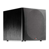
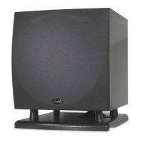
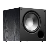
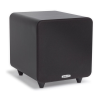
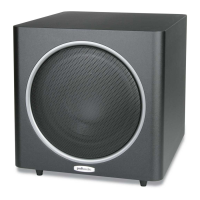
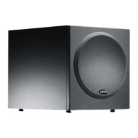
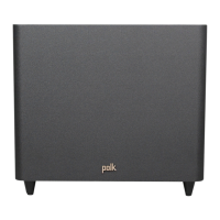
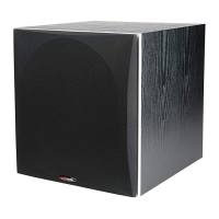
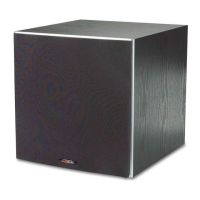
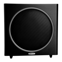
The Polk Audio PSW Series subwoofers are designed to enhance the low-frequency output of an audio system, providing deep and powerful bass. These are "powered" subwoofers, meaning they have a built-in amplifier. The manual covers three models: PSW303, PSW404, and PSW505, with the PSW505 being a "POWERED SUBWOOFER."

Usage Features

  1. Placement: The subwoofer can be placed in various locations within a room, such as an entertainment center, behind furniture, or next to a sofa or chair. For optimal performance, it should be on the same side of the room as the front speakers. Placing it near a wall or in a corner will increase bass loudness. A minimum of 6 inches (15cm) of space should be maintained between the subwoofer driver and any wall or obstruction. The subwoofer should always be placed on its base; it should never be laid on its amplifier end, as this can cause damage. The powered subwoofer is magnetically shielded, allowing for placement near video monitors, but at least 18 inches (45cm) of space should be maintained between the subwoofer and any television to prevent video distortion or discoloration.

  2. Connection Methods:

    • Method #1 (for "Satellite" Systems like Polk RM Series Speakers - Figures 6 & 7): This method involves connecting the left and right front speaker outputs of the receiver or amplifier to the speaker level inputs of the powered subwoofer using speaker wire. Then, the left and right front satellite speakers are connected to the speaker level outputs from the powered subwoofer. Alternatively, the subwoofer and front satellites can be parallel-wired from the receiver. The center channel speaker connects directly to the center channel output from the receiver, and rear surround satellites connect to the rear or surround channel outputs.
      • Receiver Setup for Method #1: For small "satellite/subwoofer" type systems, the front speakers should be set to "large," the center speaker to "normal" or "small," the surround speakers to "small," and the subwoofer to "OFF" or "none." This seemingly counter-intuitive setting ensures a full-range signal is routed to the subwoofer's low-pass filter, allowing for perfect sub/sat blending.
    • Method #2 (for Electronics with "SUB OUT" feature - Figure 8): A single RCA cable connects from the "SUB OUT" of the electronics to the LFE input of the subwoofer. This bypasses the subwoofer's variable low-pass filter, relying on the filter built into the electronics. If the "SUB OUT" signal is unfiltered, a left or right "Line Level Input" on the subwoofer should be used to utilize its low-pass crossover.
      • Receiver Setup for Method #2: Front speakers should be set to "large" or "small" depending on their output capabilities, and the subwoofer to "ON."
    • Method #3 (for Electronics with "PRE OUT" jacks - Figure 9): This method connects the left and right preamp output from the electronics to the left and right LINE LEVEL input of the subwoofer. This may require RCA "Y" cables (not supplied) to connect both the subwoofer and the power amplifier.
      • Receiver Setup for Method #3: Front speakers should be set to "LARGE," and the subwoofer to "OFF" or "NO."
  3. Speaker Wire Connections:

    • Push-Tab Terminals (PSW303 - Figure 4): To connect, push the plastic tab of a connector to open the hole, insert the bare wire, and release the tab. Ensure bare wire ends do not touch to prevent electrical shorts.
    • Binding Post Connections (PSW404 and PSW505 - Figure 5): Unscrew the binding post hex nuts several turns, insert the bare wire, and tighten the nuts. Again, ensure bare wire ends do not touch. For US owners, the binding post plugs can be carefully pried out to expose banana plug holes for banana plug connections.
  4. AC Power Connection and Auto On/Off (Figures 10, 11 & 12): The PSW series subwoofers feature auto on/off circuitry, labeled "auto" on the power switch. This automatically turns the subwoofer on when it senses a program signal and off after a few minutes of no signal. Users can also leave the subwoofer in the "on" position to avoid a brief delay when music starts. When the power switch is set to "OFF" (PSW303 or PSW404) or "STANDBY" (PSW505), it consumes a low amount of power. The PSW505 has a detachable power cord.

  5. Subwoofer Adjustments (Figures 10, 11 & 12):

    • Volume: Adjust by ear using various CDs and video sources to achieve deep, powerful bass without "boominess."
    • Low Pass: This control adjusts the frequency range of the subwoofer. For smaller main speakers, the upper range of the control is usually best, while for larger speakers, the lower end is better. The ear is the final judge. If male vocals sound "thin," increase the control; if they sound "thick" or "chesty," decrease it. This control does not operate when connected via Method #2 (LFE Input).
    • Phase Switch: Have someone switch between the 0 and 180-degree settings while listening from the preferred position. Use music with good bass and a deep male vocal. The setting that provides the best balance of deep bass and natural lower octaves of the male voice is the optimum phase tuning.

Maintenance Features

  1. Cleaning: Unplug the subwoofer from the wall outlet before cleaning. Use a damp cloth; do not use liquid or aerosol cleaners.

  2. Troubleshooting Hum: If electrical (50/60Hz) hum is present, it is often caused by "ground loops," where electrical grounds of components are not at the same potential. A common source is cable TV. Disconnecting the coaxial cable from the TV and/or VCR can help identify if this is the cause. If so, a 75-ohm ground loop isolator can be used. Faulty electrical wiring in the home or light dimmers can also introduce noise; consulting a licensed electrician or removing dimmers may be necessary.

  3. Servicing: Do not attempt to service the product yourself, as opening covers can expose dangerous voltages. Refer all servicing to qualified service personnel. Unplug the product from wall outlets and refer to qualified service personnel if:

    • The power-supply cord or plug is damaged.
    • Liquid has been spilled or objects have fallen into the product.
    • The product has been exposed to rain or water.
    • The product does not operate normally despite following operating instructions (adjusting only covered controls).
    • The product has been dropped or the cabinet damaged.
    • The product exhibits a distinct change in performance.
  4. Replacement Parts: When replacement parts are required, ensure the service technician uses parts specified by the manufacturer or parts with the same characteristics as the original. Unauthorized substitutions can result in fire, electric shock, or other hazards.

  5. Safety Check: After any service or repairs, ask the service technician to perform safety checks to ensure the product is in proper operating condition.

  6. Lightning Protection: For added protection during lightning storms or when left unattended for long periods, unplug the product from the wall outlet and disconnect the antenna or cable system to prevent damage from lightning and power-line surges.
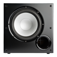
Polk Audio PSW505 Specifications

General IconGeneral
Driver Size12 inches
Amplifier Power300 Watts RMS
Peak Power460 Watts
Phase SwitchYes
Weight48 lbs
Enclosure TypeVented
InputsSpeaker level
Low Pass Crossover80 Hz - 160 Hz
Frequency Response23 Hz - 160 Hz

Related product manuals