8
1598027800 XW70K GB PKK R1.0 10.12.2013doc.docx XW70K 5/6
12 HOW TO: USE OF THE PROGRAMMING “HOT KEY”
12.1 PROGRAM A HOT-KEY FROM AN INSTRUMENT (UPLOAD)
1. Program one controller with the front keypad.
2. When the controller is ON
, insert the “HOT-KEY” and push UP button; the “uPL” message
appears followed a by a flashing “End” label.
3. Push SET button and the “End” will stop flashing.
4. Turn OFF
the instrument, remove the “HOT-KEY” and then turn it ON again.
NOTE: the “Err” message appears in case of a failed programming operation. In this case push again
button if you want to restart the upload again or remove the “HOT-KEY” to abort the operation.
12.2 PROGRAM AN INSTRUMENT BY USING A HOT-KEY (DOWNLOAD)
1. Turn OFF the instrument.
2. Insert a pre-programmed “HOT-KEY” into the 5-PIN receptacle and then turn the Controller
ON.
3. The parameter list of the “HOT-KEY” will be automatically downloaded into the Controller
memory. The “doL” message will blink followed a by a flashing “End” label.
4. After 10 seconds the instrument will restart working with the new parameters.
5. Remove the “HOT-KEY”.
NOTE: the message “Err” is displayed for failed programming. In this case turn the unit off and then on
if you want to restart the download again or remove the “HOT-KEY” to abort the operation.
13 ALARM SIGNALS
Message
Cause Outputs
P1 Thermostat probe failure
Alarm output ON; Compressor output according to
parameters Con and CoF.
P2 Second probe failure Alarm output ON; Other outputs unchanged
P3 Third probe failure Alarm output ON; Other outputs unchanged
P4 Fourth probe failure Alarm output ON; Other outputs unchanged
HA Maximum temperature alarm Alarm output ON; Other outputs unchanged
LA Minimum temperature alarm Alarm output ON; Other outputs unchanged
HA2 Condenser high temperature It depends on the AC2 parameter
LA2 Condenser low temperature It depends on the bLL parameter
dA Door open Compressor and fans restarts
EA External alarm Output unchanged.
CA Serious external alarm (i1F=bAL) All outputs OFF.
CA Pressure switch alarm (i1F=PAL) All outputs OFF
EE Data or memory failure Alarm output ON; Other outputs unchanged
noL No communication between base
and keyboard
Unchanged
The alarm message is displayed until the alarm condition is recovery.
All the alarm messages are showed alternating with the room temperature except for the “P1” which is
flashing.
To reset the “EE” alarm and restart the normal functioning press any key, the “rSt” message is
displayed for about 3 sec.
13.1 SILENCING BUZZER
Once the alarm signal is detected the buzzer can be silenced by pressing any key. Buzzer is mounted
in the keyboard and it is an option.
13.2 “EE” ALARM
The
dIXEL
instruments are provided with an internal check for the data integrity. The “EE” alarm
flashes when a failure in the memory data occurs. In such cases the alarm output is enabled.
13.3 ALARM RECOVERY
Probe alarms: “P1” (probe1 faulty), “P2”, “P3” and “P4”; they automatically stop 10 sec after the probe
restarts normal operation. Check connections before replacing the probe.
Temperature alarms “HA”, “LA” “HA2” and “LA2” automatically stop as soon as the temperature
returns to normal values.
Alarms “EA” and “CA” (with i1F=bAL) recover as soon as the digital input is disabled.
Alarm “CA” (with i1F=PAL) recovers only by switching off and on the instrument.
14 Technical data
Keyboards
Housing: self extinguishing ABS
Case: open board: facia 35x86 mm; depth 9mm
Mounting: panel mounting
Protection: IP00;
Connections: pins connections type JST EHR-2
Power supply: from XW70K power module
Display: 3 digits, red LED, 18 mm high
Optional output: buzzer.
Power module XW70K
Case: 8 DN: 140X176X148
Connections: Screw terminal block
2.5 mm
2
heat-resistant wiring and 6.3mm Faston
Power supply: 230Vac or. 110Vac
10% or 24Vac
Power absorption: 10VA max
Inputs: 4 NTC or PTC probes
Digital inputs: 1 free voltage
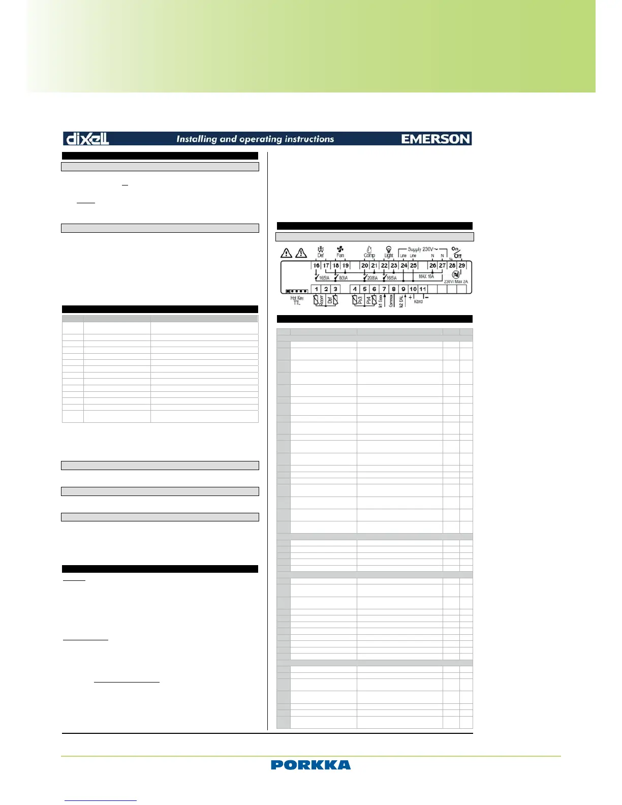
Relay outputs: Total current on loads MAX. 20A
Compressor/Valve: relay SPST 8(3) A, 250Vac
Fan: relay SPST 16(5) A, 250Vac
Defrost: relay SPST 20(8) A, 250Vac
Light : relay SPST 16(5) A, 250Vac
On/off : TRIAC 2A max, 250Vac
Serial output: TTL standard
Communication protocol: Modbus - RTU
Data storing: on the non-volatile memory (EEPROM)
Kind of action: 1B
Pollution degree: normal
Software class: A
Operating temperature: 0 to 60°C (32 to 140°F)
Storage temperature: -25 to 60°C (-13 to 140°F)
Relative humidity: 20 to 85% (no condensing)
Measuring and regulation range:
NTC probe: -40 to 110°C (-58 to 230°F)
PTC probe: -50 to 150°C (-58 to 302°F)
Resolution: 0.1°C or 1°C or 1°F (selectable)
Accuracy (ambient temp. 25°C): ±0.5°C ±1 digit
15 CONNECTIONS
15.1 XW70K
16 Default setting values
Label
REGULATION
SEt Set point LS; US -5.0 - - -
Hy Differential
[0.1 to 25.5°C]
[1 to 45°F]
2.0 Pr1
LS Minimum set point
[-55.0°C to SET]
[-67°F to SET]
-50.0
US Maximum set point
[SET to 150°C]
[SET to 302°F]
110 Pr2
ot Thermostat probe calibration
[-12 to 12°C]
[-21 to 21°F]
0.0 Pr1
P2P Second probe presence n=not present; Y=pres. Y Pr1
oE Second probe calibration
[-12 to 12°C]
[-21 to 21°F]
0.0 Pr2
P3P Third probe presence n=not present; Y=pres. n Pr2
o3 Third probe calibration
[-12 to 12°C]
[-21 to 21°F]
0 Pr2
P4P Fourth probe presence n=not present; Y=pres. n Pr2
o4 Fourth probe calibration
[-12 to 12°C]
[-21 to 21°F]
0 Pr2
odS
Outputs activation delay at start
up
0 to 255 min 0 Pr2
AC Anti-short cycle delay 0 to 30 min 1 Pr1
Ac1 Second compressor delay 0 to 255 sec 5 Pr2
rtr P1-P2 percentage for regulation 0 to 100 (100=P1 , 0=P2) 100 Pr2
CCt
Compressor ON time during fast
freezing
0.0 to 23h50min, res. 10 min 0.0 Pr2
CCS Set point for continuous cycle
[-55.0 to 150.0°C]
[-67 to 302°F]
-5 Pr2
Con
Compressor ON time with faulty
probe
0 to 255 min 15 Pr2
CoF
Compressor OFF time with faulty
probe
0 to 255 min 30 Pr2
DISPLAY
CF Temperature measurement unit °C; °F °C Pr2
rES Resolution (integer/decimal point)
rEd Remote display P1; dtr P1 Pr2
dLy Display temperature delay 0.0 to 20min00sec, res. 10 sec 0 Pr2
dtr P1-P2 percentage for disply 1; 100 50 Pr2
DEFROST
tdF Defrost type EL; in EL Pr1
dFP
Probe selection for defrost
termination
nP; P1; P2; P3; P4 P2 Pr2
dtE Defrost termination temperature
[-50.0 to 150°C]
[-58 to 302°F]
8.0 Pr1
idF Interval between defrost cycles 1 to 120 h 6 Pr1
MdF (Maximum) length for 1° defrost 0 to 255 min 30 Pr1
dSd Start defrost delay 0 to 99 min 0 Pr2
dFd Displaying during defrost rt; it; SEt; dEF; dEG it Pr2
dAd MAX display delay after defrost 0 to 255 min 30 Pr2
Fdt Draining time 0 to 60 min 0 Pr2
dPo First defrost after start up n; Y n Pr2
dAF Defrost delay after fast freezing 0.0 to 23h50min, res. 10 min 0.0 Pr2
FANS
FnC Fans operating mode C-n; C-y; O-n; O-y o-n Pr1
Fnd Fans delay after defrost 0 to 255 min 10 Pr1
FCt
Differential of temperature for
forced activation of fans
[0 to 50°C]
[0 to 90°F]
10 Pr2
FSt Fans stop temperature
[-55.0 to 50°C]
[-67 to 302°F]
2 Pr1
Fon Fan on time with compressor off 0 to 15 min 0 Pr2
FoF Fan off time with compressor off 0 to 15 min 0 Pr2
FAP
Probe selection for fan
management
nP; P1; P2; P3; P4 P2 Pr2
Technical and Service manual
Porkka reserves the right to make product alterations at any time and can not be held responsible for any printing errors or omissions.
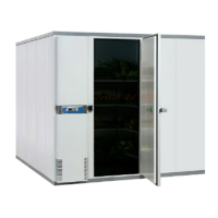
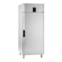
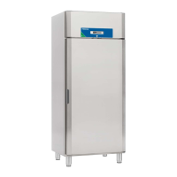
Inventus upright refrigerators and freezers
User manual - Control unit XW70K AND D50K
 Loading...