10
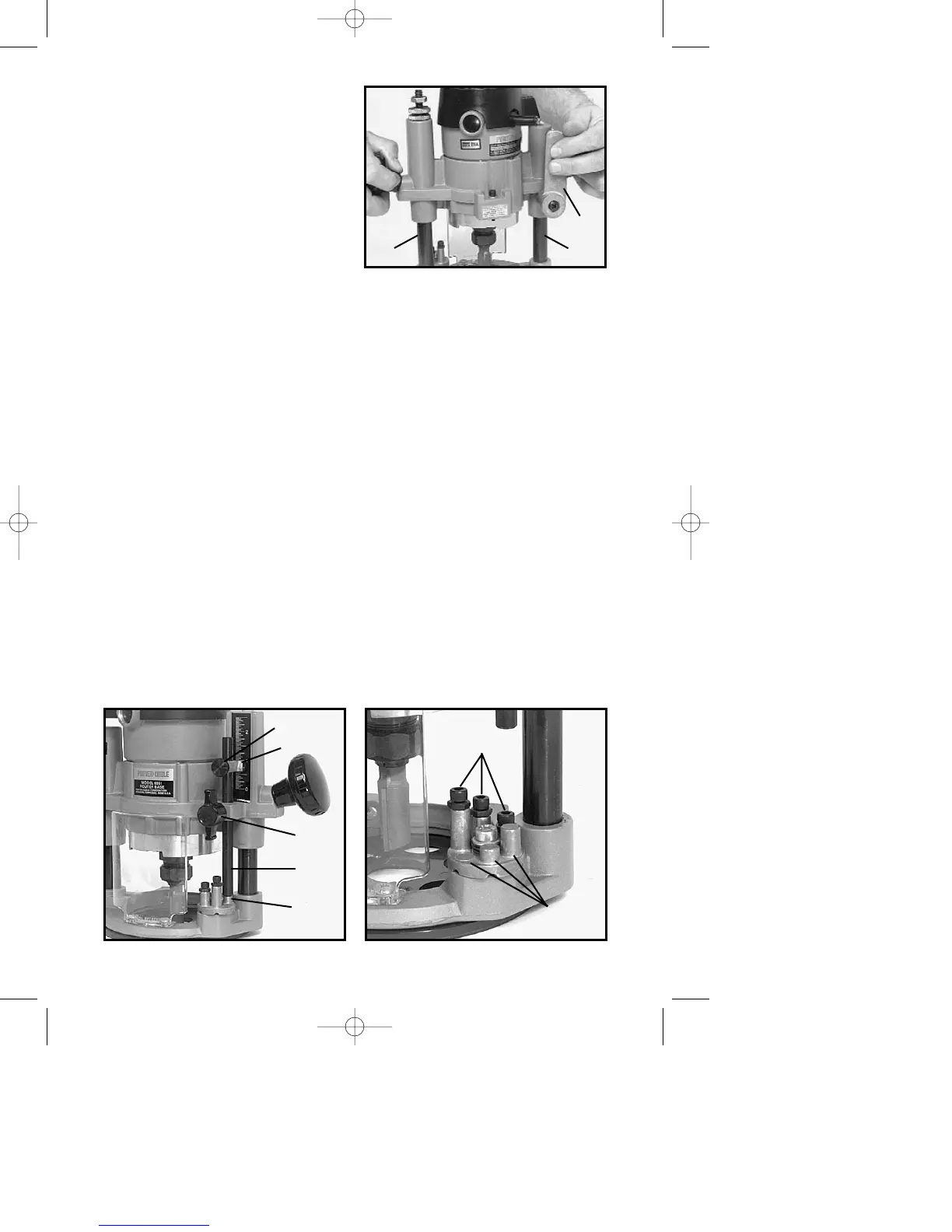
DO NOT ALLOW WRENCHES TO
CONTACT COLUMNS (A) Fig. 9,
AS COLUMNS MAY BE
DAMAGED, RESTRICTING
PLUNGE ACTION.
NEVER TIGHTEN COLLET NUT
WITHOUT BIT INSERTED. TO DO
SO MAY DAMAGE COLLET.
4. To remove bit, reverse the
foregoing procedure. If bit does not
remove easily, tap the collet nut with
wrench to release bit.
ADJUSTING PLUNGE BASE
1. CAUTION: DISCONNECT TOOL FROM POWER SOURCE.
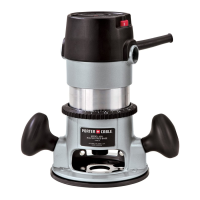
2. Loosen depth rod locking knob (A) Fig. 10, and depth indicator knob (D)
Fig. 10, allowing the depth rod (E) Fig. 10, to contact one of the turret stops
(B) Fig. 10.
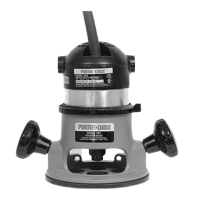
Normally the deepest desired cut is set with the depth rod resting on the
shortest turret stop (A) Fig. 11. The other two fixed stops then provide
reduced cutting depths of
1
/4" and
1
/2" respectively. The three adjustable stops
may be adjusted to any desired height. Any combination of fixed and/or
adjustable stops may be utilized to achieve the desired depths required for a
particular job.
3. Release plunge mechanism by pulling the locking lever (B) Fig. 9, to the
left and lower plunge mechanism until the router bit just touches the work
surface. Release lever and push to the right to lock mechanism in this
position.
4. Tighten depth rod locking knob.
5. Position depth indicator (C) Fig. 10, at “0” position and tighten knob.
6. Loosen depth rod locking knob and raise depth rod until indicator aligns
with the graduation representing the desired depth of plunge. (The example
in Fig. 12 shows setting for 1" plunge.)
Fig. 9
B
AA
Fig. 10 Fig. 11
D
C
A
E
B
B
A