6
FUNCTIONAL DESCRIPTION
FOREWORD
Your Porter-Cable Cordless Driver/Drill is designed to drill holes and drive
fasteners in various materials as indicated in the following chart:
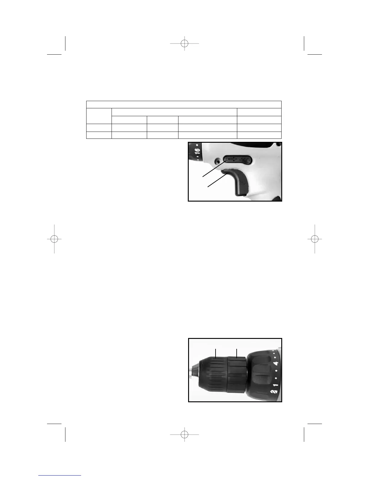
SWITCH OPERATION
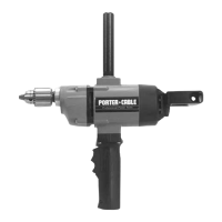
Squeeze trigger switch (A) Fig. 1, to
start motor. Release trigger to stop
motor. As the trigger is squeezed the
motor speed increases.
NOTE: A low volume, high
pitched tone may be heard while
the switch is in the variable speed
mode. This is normal.
FORWARD/REVERSE
• Make sure trigger switch (A) Fig. 1, is in OFF position before attempting to
change direction of rotation.
• Push button (B) Fig. 1, toward left side of drill for FORWARD (clockwise)
rotation.
• Push button (B) Fig. 1, toward right side of drill for REVERSE (counterclock-
wise) rotation.
• Place button (B) Fig. 1, in center position to lock trigger switch in OFF
position.
ELECTRIC BRAKE
When the trigger switch is released, an electric brake automatically engages
to stop spindle rotation.
INSTALLING AND REMOVING DRILL AND SCREWDRIVER BITS
1. CAUTION: Always set reversing button to center (locked OFF) position
when installing and removing bits.
2. The three-jaw chuck is designed
for self-centering of the bit. Open jaws
large enough by turning outer sleeve
(A) Fig. 2, counterclockwise, when
viewing the chuck from the bit end, so
that bit shank can be inserted easily.
3. Clean and insert smooth end of
bit as far as it will go into the chuck, or
up to the flutes for small bits.
Fig. 1
B
A
Fig. 2
A
B
MAXIMUM CAPACITIES
SPEED
DRILLING DRIVING
RANGE MILD STEEL ALUMINUM WOOD SELF-FEED BIT WOOD SCREWS
LOW
3
/
8
"
3
/
8
"1"
3
/
8
"
HIGH
3
/
8
"
3
/
8
"
1
/
2
" #10