EasyManua.ls Logo

Porter-Cable 892 User Manual

Porter-Cable 892
23 pages
To Next Page IconTo Next Page
Page #1 background imageLoading...
Page #1 background image
Instruction
manual
The Model and Serial No. plate is located on the main
housing of the tool. Record these numbers in the
spaces below and retain for future reference.
Model No. ______________________________________
Type ___________________________________________
Serial No. _______________________________________
IMPORTANT
Please make certain that the person who is
to use this equipment carefully reads and
understands these instructions before
starting operations.
ESPAÑOL: PÁGINA 23
FRANÇAISE : PAGE 45
To learn more about Porter-Cable
visit our website at:
http://www.porter-cable.com
Copyright © 2005 Porter-Cable Corporation
Part No. 903618 - 01-17-05
MODEL 891
MODEL 892
MODEL 8931
Routers
Question and Answer IconNeed help?

Do you have a question about the Porter-Cable 892 and is the answer not in the manual?

Porter-Cable 892 Specifications

General IconGeneral
Voltage120V
Soft StartYes
Spindle LockYes
Motor Power2-1/4 HP
Amperage11 Amps
Collet Size1/4 inch and 1/2 inch
Base TypeFixed and Plunge
Depth AdjustmentMicro-adjustment

Summary

Important Safety Instructions

Safety Guidelines and Definitions

California Proposition 65 Warning

Warning about dust exposure from power tools and associated health risks.

General Safety Rules

Electrical Safety

Precautions to prevent electric shock, including cord care and grounding.

Personal Safety

Advice on operator awareness, common sense, and using protective equipment.

Additional Specific Safety Rules

Handling Cutting Tools Safely

Rules for safe handling of cutting tools and avoiding contact with hot bits.

Dust and Airborne Particle Precautions

Warnings and precautions regarding dust exposure and respiratory protection.

Wearing Safety Equipment

Requirements for eye and hearing protection compliant with safety standards.

Functional Description and Assembly

Installing and Removing the Bit (Models 891 and 892)

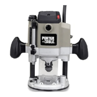
Step-by-step instructions for bit installation and removal on specific models.

Installing and Removing Bits Using Spindle Lock Actuator (Model 892)

Installing the Motor

Adjusting Depth of Cut

Adjusting Sub-Base Alignment

8931 Plunge Base and Vacuum Hose

Installing and Removing the Bit (8931 Plunge Base)

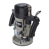
Instructions for bit installation and removal on the 8931 plunge base model.

Installing and Removing Bits Using Spindle Lock Actuator (Table Mounted)

Adjusting the Plunge Base

Adjusting Plunge Locking Lever

Operation: Connecting to Power Source

Starting and Stopping the Motor

Variable Speed Control

Using the Tool

Avoiding Climb-Cutting

Warning and caution about climb-cutting and maintaining control.

Maintenance and Troubleshooting

Service and Warranty

Related product manuals