10
11
ASSEMBLY
To prevent accidental operation, turn off and unplug tool before
performing the following operations. Failure to do this could result in serious
personal injury.
ATTACHING THE WHEEL GUARD - FIG. 2
NEVER GRIND OR BRUSH WITHOUT GUARD IN PLACE.
• Place the tool on a table, with the spindle (9) facing up.
• Place the spring washer (8) over the spindle and locate it on the shoulder (10).
• Place the guard (4) onto the tool as shown.
• Place the flange (7) over the spindle with the protruding pips towards the guard. Make
sure that the holes in the flange align with the screw holes.
• Secure the flange with the screws (6). Make sure that the screws are fully tight and that
the guard can be rotated.
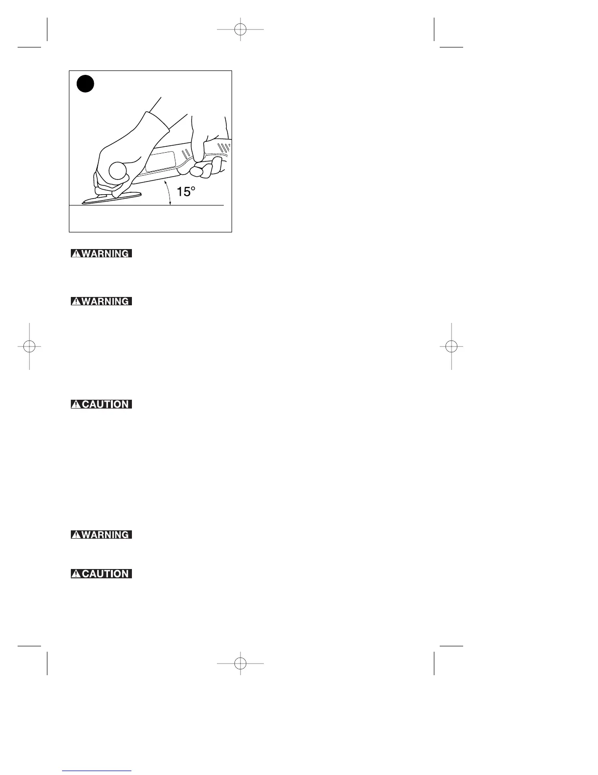
REMOVING THE WHEEL GUARD (FOR SANDING ONLY) - FIG. 3
To prevent loss of control, do not set tool down until accessory has
completely stopped turning.
This tool is fitted with a guard. For sanding only, you can remove the guard as follows:
• Remove the outer flange, disc and inner flange if they have been attached.
• Use a screwdriver to remove the screws (6).
• Remove the flange (7), guard (4) and spring washer (8). Store these parts carefully.
ADJUSTING THE GUARD
The guard can be rotated 90°.
• Rotate the guard as required.
FITTING THE SIDE HANDLE
• A three position auxiliary handle (3) is furnished with your grinder and can be screwed
into either side of the grinder housing as well as into the top.
This handle SHOULD BE USED AT ALL TIMES to maintain complete
control of the tool. Always make sure the handle is tight.
FITTING AND REMOVING DEPRESSED CENTER WHEELS - FIG. 4 - 6
Never use any depressed-center wheels without the proper guard.
FITTING - FIGURE 4,5
• Fit the guard as described above.
• Place the inner flange (11) onto the spindle (7) as shown (fig. 4). Make sure that the