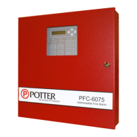
What to do if my Potter Control Panel shows a NAC “##”: Shorted error?
- JjshermanAug 1, 2025
To resolve the 'NAC “##”: Shorted' error on your Potter Control Panel, you should locate the short circuit and repair it.

What to do if my Potter Control Panel shows a NAC “##”: Shorted error?
To resolve the 'NAC “##”: Shorted' error on your Potter Control Panel, you should locate the short circuit and repair it.
How to fix SLC LOOP SHORTED error on Potter PFC-6075 Control Panel?
If your Potter Control Panel displays 'SLC LOOP SHORTED', you will need to locate the short circuit on the SLC loop and repair it.
What to do if Potter PFC-6075 Control Panel displays SLC “##”: DUP ADDR?
If your Potter Control Panel is showing 'SLC “##”: DUP ADDR', you should manually reassign the address of one of the devices connected to the SLC loop.
How to troubleshoot SLC 1: Missing error on Potter PFC-6075?
If your Potter Control Panel displays 'SLC 1: Missing', you should check if the device is currently operating or connect the device to the SLC loop.
How to fix Keypad “##”: Missing error on Potter PFC-6075 Control Panel?
If your Potter Control Panel displays 'Keypad “##”: Missing', check the wiring and programming.
| Zones | 75 |
|---|---|
| SLC Loops | 1 |
| Input Voltage | 120/240 VAC |
| Output Voltage | 24 VDC |
| Operating Temperature | 32 to 120°F (0 to 49°C) |
| Enclosure Type | Metal |
| Mounting | Surface |
Details circuit separation and wiring type requirements for the main board.
Explains how to calculate battery size for standby and alarm times.
Covers installation procedures for the SLC.
Lists mandatory wiring parameters for SLC installation.
Explains wiring analog detectors and their base units.
Provides wiring examples for various addressable modules.
Details methods for assigning addresses to SLC devices.
Covers installation of NAC circuits.
Explains configuration of Input/Output circuits.
Covers installation of the CA-6075 Class A expander card.
Discusses connecting accessory devices via the P-Link bus.
Explains setting addresses for P-Link devices using dip switches.
Covers installation of remote annunciators.
Explains installation of LED-16 annunciators.
Covers installation of DRV-50 LED drivers.
Covers installation of RLY-5 Relay Board modules.
Covers installation of the FCB-1000.
Covers installation of the FIB-1000.
Details wiring procedures for the FIB-1000.
Covers installation of the SPG-1000.
Covers installation of the UD-1000 Digital Alarm Communicator Transmitter.
Overview of panel components like LCD, LEDs, and buttons.
Details various programming options and their settings permitted by UL864.
Covers zone types, alarm count, silenceable, and latching attributes.
Specifies the function and type of SLC devices.
Overview of LEARN function and recommended programming steps.
Instructions for installing the panel configuration software.
Details how to use the LEARN mode for device configuration.
Instructions for connecting PC to the panel via network.
Step-by-step guide for uploading and downloading data.
Instructions for uploading configuration files from panel to PC.
Instructions for downloading configuration files to the panel.
Steps to enable remote access for data transfer.
Steps to download configuration files to the panel.
Instructions to upload history and detector status reports.
Instructions to generate reports on sensor sensitivity settings.
How to print History and Detector Status reports.
Overview of panel configuration software navigation and features.
Provides a summary of menu options and their descriptions.
Details how to set remote access user name and password.
Enabling Day/Night sensitivity and setting up holidays.
Creating user profiles with different access rights.
Overview of panel's built-in e-mail capabilities.
Steps to connect the panel to a network for e-mail.
Scheduling and setting up e-mail reports and addresses.
How to send reports from the panel via data transfer.
How to request reports from a remote PC via e-mail.
Details how to interpret received system status e-mails.
Setting up customizable e-mail reminders.
Defines programming by mapping devices and configuring zones.
Explains creating relationships between devices and zones.
Customizing device behavior by grouping into up to 99 zones.
Details zone attributes like name, alarm count, silenceable, latching.
Details output patterns, day/night sensitivity, and timers.
Steps for creating new zones and managing them.
Customizing zone attributes like name and style.
Defining device roles, behavior, and names.
Describes NAC and I/O circuit configuration functions.
Lists configuration options for SLC points.
Steps to display and configure points in the software.
How to configure individual points with names and functions.
Steps to configure points in a selected range.
Steps to configure multiple specific points.
Details programming IP reporting accounts.
Customizing format and settings for IP reporting accounts.
Lists error messages and recommended actions for troubleshooting.