MFG. #5401161 - REV D
09/12
PRINTED IN USA PAGE 3 OF 8
MODEL PS40 (VdS)
SUPERVISORY PRESSURE SWITCH
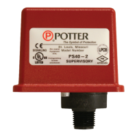
Break out thin section of divider to provide path for wires when wiring both
switches from one conduit entrance.
One Conduit Wiring
Fig. 6
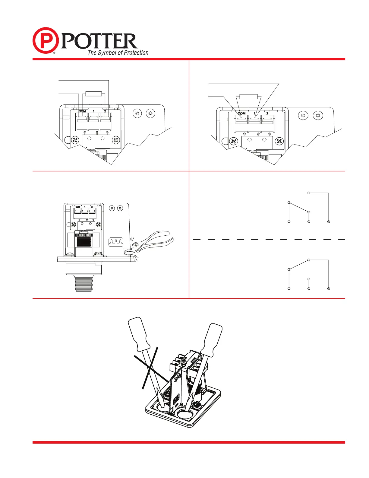
Fig. 8
Fig. 9
Removing Knockouts
C
C
C
12
C
12
LOW PRESSURE SWITCH
HIGH PRESSURE SWITCH
Switch Operation
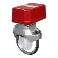
Low Pressure Signal Connection
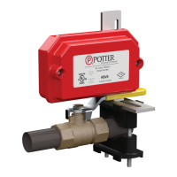
High Pressure Signal Connection
Fig. 5
Fig. 7
(With normal system pressure)
Terminal
C: Common
1: Closed when installed under normal
system pressure.
2: Open when installed under normal
system pressure. Closes on pressure
drop. Use for low air signal.
Terminal
1: Open when installed under normal
system pressure. Closes on
increase in pressure. Use for high
air signal.
2: Closed under normal system
pressure.
 Loading...