POTTERTON COMMERCIAL PRODUCTS DIVISION
INSTALLATION, OPERATION AND MAINTENANCE MANUAL
SECTION 3
PARAMOUNT
PAGE 9
Explanations on Hydraulic Diagrams
For certain applications it is necessary to set the
boiler controller to the correct hydraulic setting, below
are the settings required.
Application example 1a:
- Hydraulic system “2” (Factory Preset)
Application example 1d:
- Hydraulic system “2” (Factory Preset)
- Set parameter 618 to 6
- Connect flow sensor B6 to the temperature
module CITF.
Header pump M5 (exit M5):
- Set Parameter 615 to 9 and parameter 632 as
follows: b2 = 1, b3 = 1
- Connect primary loop pump to exit M5
Connect pump for CTC to M1
Application example 2a:
- Set hydraulic system to “50” ⇒ Set Parameter
552 to 50
Alternatively, 1 mixer circuit with zone control (M5)
- Set hydraulic system to “66” ⇒ Set Parameter
552 to 66
Application example 2b:
- Set hydraulic system to “50” ⇒ Set Parameter
552 to 50
Header pump M5 (exit M5):
- Set parameter No 615 to 9 and parameter 632,
b1 = 1
Special Applications
For other applications please contact the Potterton
Commercial Technical department who will be
pleased to discuss any requirements you have.
INSTALLATION
Connecting Heating Circuit: Connect heating circuit
to boiler flow and boiler return with flat sealing
threaded fittings. Welded or brazed connection is not
permissible (guarantee void). We recommend
installation of a filter in the heating return. On old
systems, the entire heating system should be flushed
thoroughly before installation. Install isolation valves
in flow and return.
Safety Valve: Ensure that the blow-out pipe for the
safety valve is installed so that a pressure increase,
when the safety valve actuates, is not possible. The
pipe should not lead outside, the outlet must be free
and observable. It must be possible for any heating
water escaping to drain without danger e.g. through a
trap.
Sealing and Filling the System: Fill the heating
system through the return on the PARAMOUNT. For
this purpose, open the non-return valve
(PARAMOUNT 40 ONLY, SEE Fig.1) after filling,
move the non-return valve back into the operating
position. Check for leakage (max. water test pressure
3 bar).
Condensate: It is only permissible to drain the
condensate directly into a domestic sewer system
when the system consists of corrosion-resistant
materials (e.g. PP pipe, stoneware etc.). If this is not
applicable, it is possible install the POTTERTON
condensate treatment tank. It must be possible for
the condensate to drain freely into a funnel. A trap
must be installed between the funnel and sewer
system. Root the condensate hose from the
PARAMOUNT out of the boiler on the left, next to the
heating flow.
Caution: Before commissioning, fill the condensate
drain in the boiler with water. For this purpose, fill
0.25L of water into the flue fitting before installing the
flue pipe.
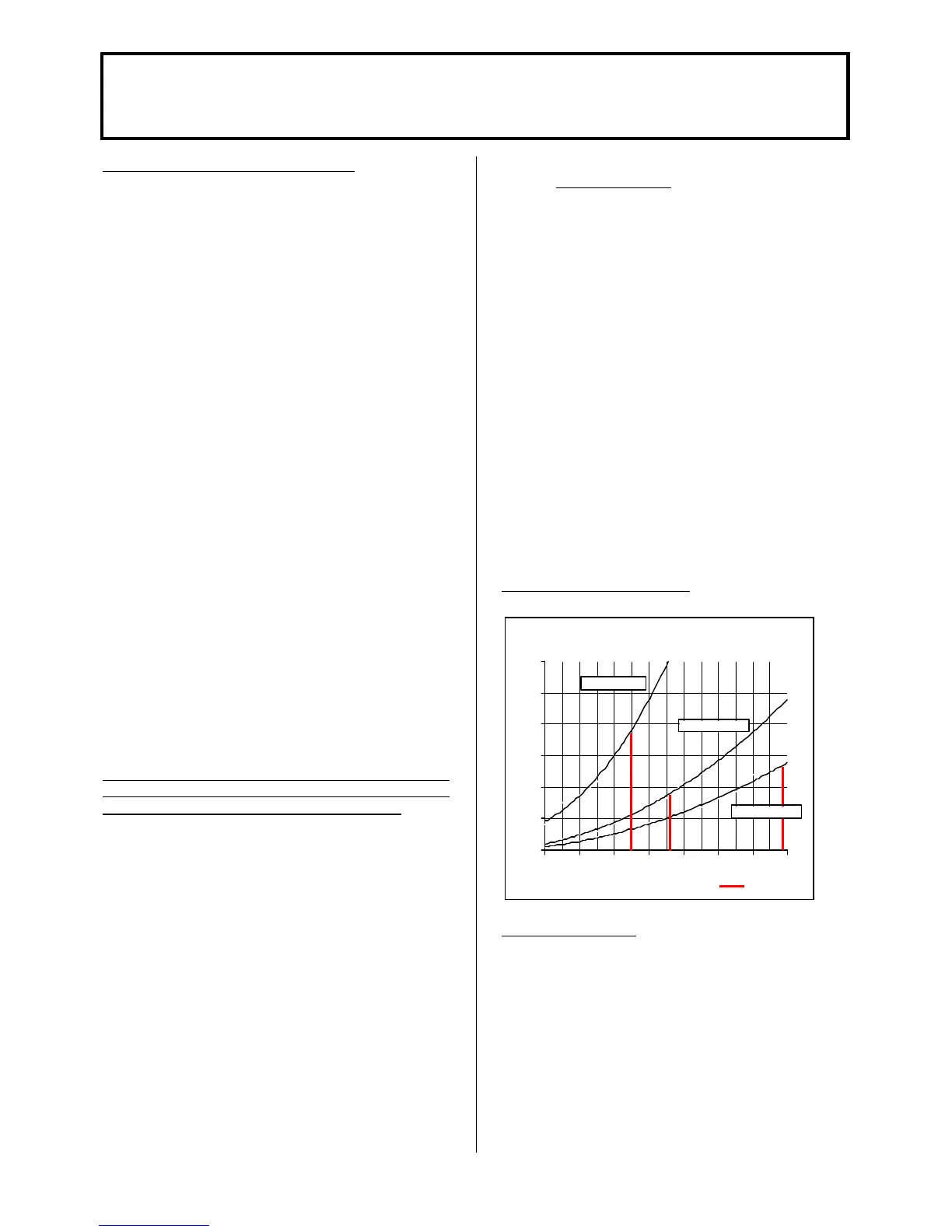
Fig 3. Hydraulic resistance.
FLUE CONNECTION
The flue pipe must be installed for flue temperatures
below 120°C for operation of the Paramount as a
condensing boiler (Flue Type B). Observe the
installation instructions, which are included with the
flue pipe when installing.
HYDRAULIC PRESSURE DROP
0
10
20
30
40
50
60
0.3 0.5 0.7 0.9 1.1 1.3 1.5 1.7
 Loading...

