POTTERTON COMMERCIAL PRODUCTS DIVISION
INSTALLATION, OPERATION AND MAINTENANCE MANUAL
SECTION 4
PARAMOUNT
PAGE 13
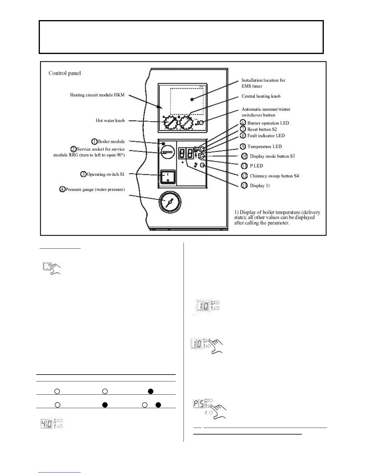
Commissioning
• Switch on the mains switch (3) on the
boiler module (1). When sufficient water
pressure is present the PARAMOUNT
can start operating.
• Set the central heating knob of the HKM to the
desired boiler temperature value (without) outdoor
temperature sensor) or to the desired room
temperature value (if an outdoor temperature sensor
is connected). While turning the knob the set point is
displayed.
• Set the hot water knob to the desired hot water
temperature value. While turning the knob, the set
point is displayed.
• If the summer/winter switch is set to “Automatic” or
“Winter”, the PARAMOUNT starts operating in the
heating or DHW mode. If it is set to “Summer” the
PARAMOUNT starts operating in the DHW mode.
Manual summer Manual Winter Automatic mode
LED “Auto” LED “Auto” LED “Auto”
LED “Θ” LED “Θ” LED “Θ”
or
•The current boiler temperature is
indicated on the display (13) and the
green burner operating LED (6)
illuminates when the burner is in
operation.
Note: If an outdoor temperature sensor is not
connected the PARAMOUNT is heated up to a boiler
temperature of approx. 55°C.
Fault Display (8)
• If the burner does not start up the red
fault indicator LED (8) and display (13)
flash with the error code
Reset Button (7)
• The PARAMOUNT can be reset with
the reset button (7) and the burner is
then ready for a new start attempt. After
a number of unsuccessful start attempts
inform a heating engineer depending on
the error code present.
Display Mode Button (10)
• With the display mode button (10) the
values (parameters, actual values or
nominal values) listed can be checked
and changes made.
CO
2
COMMISSIONING AND SETTING /
CONVERSION TO OTHER TYPES OF GAS
Fig. 5
 Loading...

