SECTION 5 POTTERTON COMMERCIAL PRODUCTS DIVISION
INSTALLATION, OPERATION AND MAINTENANCE MANUAL
PAGE 22
PARAMOUNT
Turning off S/W changeover: The automatic S/W
changeover feature operates with a switching
difference of + 1K. If a temperature of equal to or
greater than 30°C is set. in program No.516,
changeover is not accomplished.
519 (TiAussen/Norm) (modulating pump only):
NOT REQUIRED U.K.
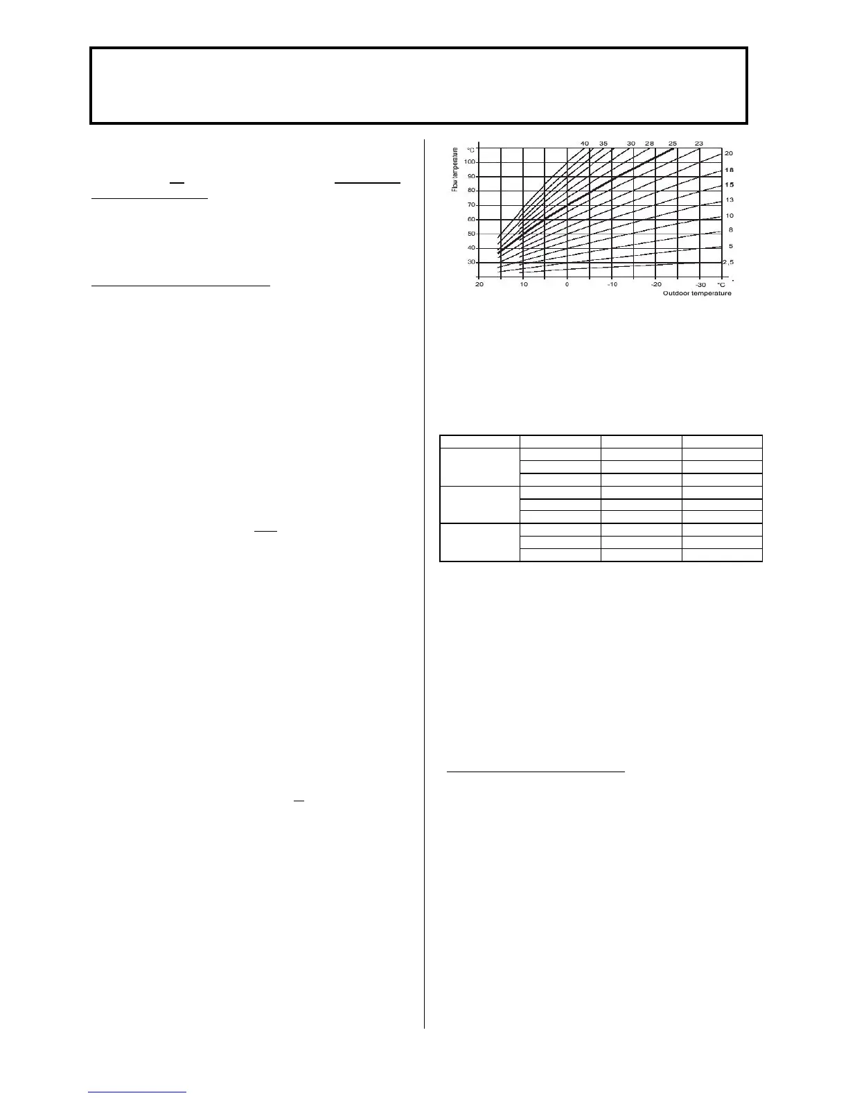
ADJUSTING HEATING CURVE
520 (dTrAvsenk) Night Setback room temperature
setting: The room temperature setting is reduced by
the value set here by a connected timer (e.g. EMS) in
night setback mode. Adjustment range 0 to 10K the
room temperature setting made here is included in
calculating the boiler temperature setting when
outdoor compensation control is used.
521 (dTkTrNenn) (modulating pump only): NOT
REQUIRED IN THE U.K.
532 (Sth1) bzw. 533 (Sth2) Heating curve
steepness HC1 or 2: When used without the room
control module RRG the steepness of the heating
curves can be set here for the CTC (HC 1) or VTC
(HC 2). Note: When used with a RRG, the heating
curves in the RRG are effective and can be set there!
Standard value for heating curve (delivery state): The
settings at the heating engineer level for the BMU
control centre can be made with the room control
module RRG.
The parameters, which can be set are shown in
Table 5.
The factory settings for the heating curve as follows:
- CT heating circuit 25 and
- VT heating circuit 25 (See below)
The heating curve can be adjusted as follows,
depending on the system equipment.
- with room control module RRG: On heating
engineer level for RRG program No.70 or 80.
The values from the RRG write over
parameters “532” and “533”!
- with heating circuit module HKM: On boiler
module parameter “P 5” or with RRG as
service unit (Table 5)
534 (DtR1) and (DtR2) Correction of room
temperature setting HC1 and 2: These two
parameters shift the heating curve for heating circuit
1 and 2 parallel. If the room temperature setting is
not achieved with the heating curve set, this allows
adaptation. (See table below)
536 (NHZmAX) Fan maximum speed for output
adjustment of Paramount: The maximum boiler output in
the heating mode can be limited by reducing the speed of
the fan to the desired output. For this purpose, set the
maximum speed in program no. 536 (NhzMax) and
program no.541 (PhzMax) according to Table 9.
Table 7: Max boiler output in heating mode (guide values)
Model Max heat load Para 536 rpm Para 541 %
32 4900 75
22 3300 44
Paramount 40
11 1700 18
50 4900 76
45 4400 69
Paramount 60
40 3900 60
60 4750 80
50 3950 67
Paramount 80
40 3150 53
537 (NqmodNenn) Speed stage at design point of
heating system: NOT REQUIRED IN THE U.K.
538 (NqmodMin) Min pump speed for heating system:
NOT REQUIRED IN THE U.K.
541 (PhzMax) Degree of modulation in heating
mode: In order to ensure optimum operation of the
PARAMOUNT, it is necessary to adapt the PWM
signal (% increments) for the max. degree of
modulation in the heating mode to the maximum
speed, program No. 536 (NhzMax) (see Table 7).
SETTINGS FOR THE BURNER
542 (PminHuKw) Min boiler input in kW: Differ
depending on type of boiler:
PARAMOUNT 40 → 9kW or
PARAMOUNT 60 → 14 kW or
PARAMOUNT 80 → 20 kW
543 (PmaxHuKw) Max boiler input in kW: Differ
depending on type of boiler:
PARAMOUNT 40 → 38 kW or
PARAMOUNT 60 → 58 kW or
PARAMOUNT 80 → 77 kW
Programs No. 542 and 543 serve only for indication
of the specific boiler output (no function) and
balancing the output when the cascade controller
EUROCONTROL BCA 2 is used.
 Loading...

