SECTION 6 POTTERTON COMMERCIAL PRODUCTS DIVISION
INSTALLATION, OPERATION AND MAINTENANCE MANUAL
PAGE 34
PARAMOUNT
FAULT MESSAGES
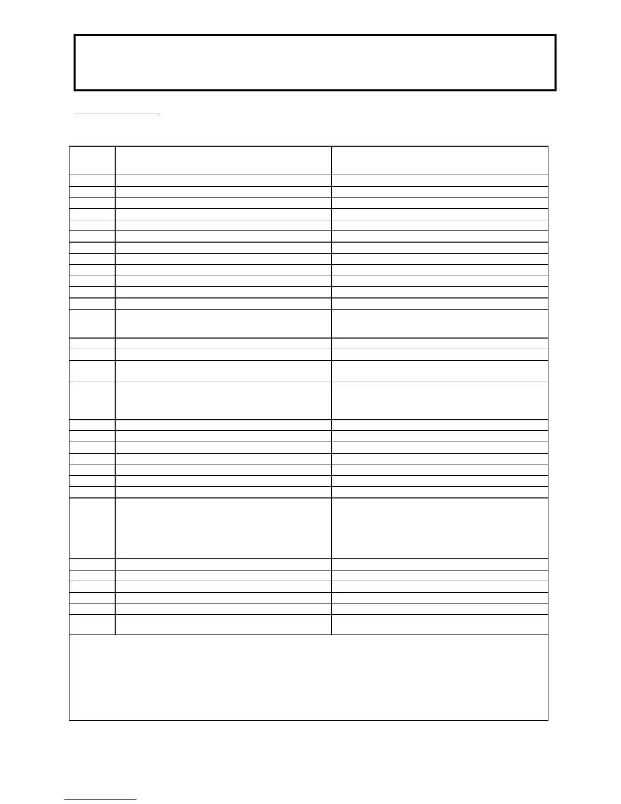
Table 11 Fault Messages (display 13 flashing)
Display
flashing
(Code No)
Description Explanations
Possible caused and function sequence
10 Outdoor temperature sensor short circuit or discontinuity Check connection and outdoor temperature sensor
20 Boiler flow sensor short circuit or open circuit Check connection 2)
40 Boiler return sensor short circuit or open circuit Check connection 2)
50 Hot water sensor 1 short circuit or open circuit Check connection; emergency operation 2)
52 Hot water sensor 2 short circuit or open circuit Check connection 2) (not present)
61 Fault, room control module RRG Check room control module RRG
62 Wrong room control module connected Connect compatible room control module
81 Short circuit on LPB bus or no bus feed Check bus
82 Address conflict on LPB bus (EUROCONTROL) Check addresses of connected control modules
91 EEPROM data loss Internal BMU error, process sensor, change BMU
92 Hardware error internal BMU error, process sensor, change BMU
100 Two time master Check EUROCONTROL time master
110 Limit stat tripped Allow unit to cool dow n and reset. If fault occurs several
times, notify heating engineer 1) temperature stat open
circuit (possible short circuit in gas valve) 3)
111 Max. temperature tripped No heat requirement, pump defective, radiator valves closed
119 Water pressure switch tripped Check water pressure and add water if required 2)
132 Safety switch off e,g, contact F7 open (Pressure Switch)
Possible low gas pressure
133 No flame detected (no flame message after expiration of
safety time)
Reset, if fault occurs a number of time, notify heating
engineer, insufficient gas 9see Page 20) check polarity of
line power connection, ignition electrodes and ionisation
current 1) 2)
134 Flame failure during operation Automatic restart attempt by PARAMOUNT
135 Incorrect air supply Fan speed above or below speed threshold 2)
140 Impermissible LPB segment number or equipment number Check setting on EUROCONTROL
148 Incompatibility between LPB interface basic unit Check setting on EUROCONTROL
151 Internal error in BMU Check parameters (Tables 5 and 6) heating engineer 1) 2)
152 Error in BMU parameter settings Repeat parameter settings
153 PARAMOUNT disabled Press reset button 1)
154 Temperature fault 1. Boiler temperature rises too fast.
2. Return temperature higher than flow temperature
3. Return temperature more than 50°C below flow temp,
check water flow through boiler.
4. Parameter incorrectly set (tables 5 & 6) check
parameters 1) 3)
160 Fan speed error Fan speed not reached 1)
161 Max. speed exceeded Max. fan speed exceeded
180 Chimney sweep function active 4)
181 Controller stop mode active 4)
183 PARAMOUNT in parameter setting mode 1)
bu Faulty connection between Control unit and LMU Check wiring in-between and replace control unit if
necessary
Display of 3-digit error messages: The 1 in the number 100 is displayed alternately with the 10’s position
1) Switch off and disable; can be enabled only with reset
2) Switch off, start prevention; starts backup after fault disappears
3) Check parameters according to Table 8 and program basic settings or
check value “b 0” (internal BMU-SW diagnostic code, Table 5) and correct parameter error according to error specification!
4) Error display only, no switch off.
 Loading...

