POTTERTON COMMERCIAL PRODUCTS DIVISION
INSTALLATION, OPERATION AND MAINTENANCE MANUAL
SECTION 6
PARAMOUNT
PAGE 33
CONTROL CENTRE
Electrodes: To ensure proper function of the
ignition and ionisation, ensure that installation
length and spacings are observed as shown in
Fig.11.
The ionisation current should have the following
values for burner operation:
- at min. output > 5 µ A, DC (switching threshold at
0.7 µA, DC)
- at max. output > µA, DC
Ionisation Current Indicator: The current ionisation
current can be checked as follows directly in µA:
- on boiler module (1) under parameter “C 1”
- using room control module RRG (optional extra)
Function Description: Control and monitoring of
burner by BMU control centre with ionisation
electrode.
• Automatic start-up according to program with
monitoring of flame formation
The operation itself can be varied using parameters
• The display on the control panel indicates the
individual operating or program states with
numbers or letters (see Table 10)
Reset: Following Reset (power OFF/ON) the BMU
control centre starts in the Home mode.
Fault Switch Off: Safety switch-off in the event of
flame failure during operation. After each safety
switch-off, a new ignition attempt is accomplished
according to program. If this does not lead to flame
formation, a fault shut-off is accomplished. In the
event of a fault shut-off, press the Reset button on
the control panel.
In the event of fault (red light) the numbers on the
display on the control panel indicates the cause of
the fault (see Table 11).
Burner Does Not Operate: No power to control
centre, e.g. no “Burner ON” signal from heating
circuit control (see Table 11).
Burner Goes to Fault: Without flame formation: No
ignition, ionisation electrode has short circuit to
ground, no gas. In spite of flame formation, burner
goes to fault after expiration of safety time:
Ionisation electrode defective or dirty. Ionisation
electrode not submerged in flame, boiler connected
with reverse polarity.
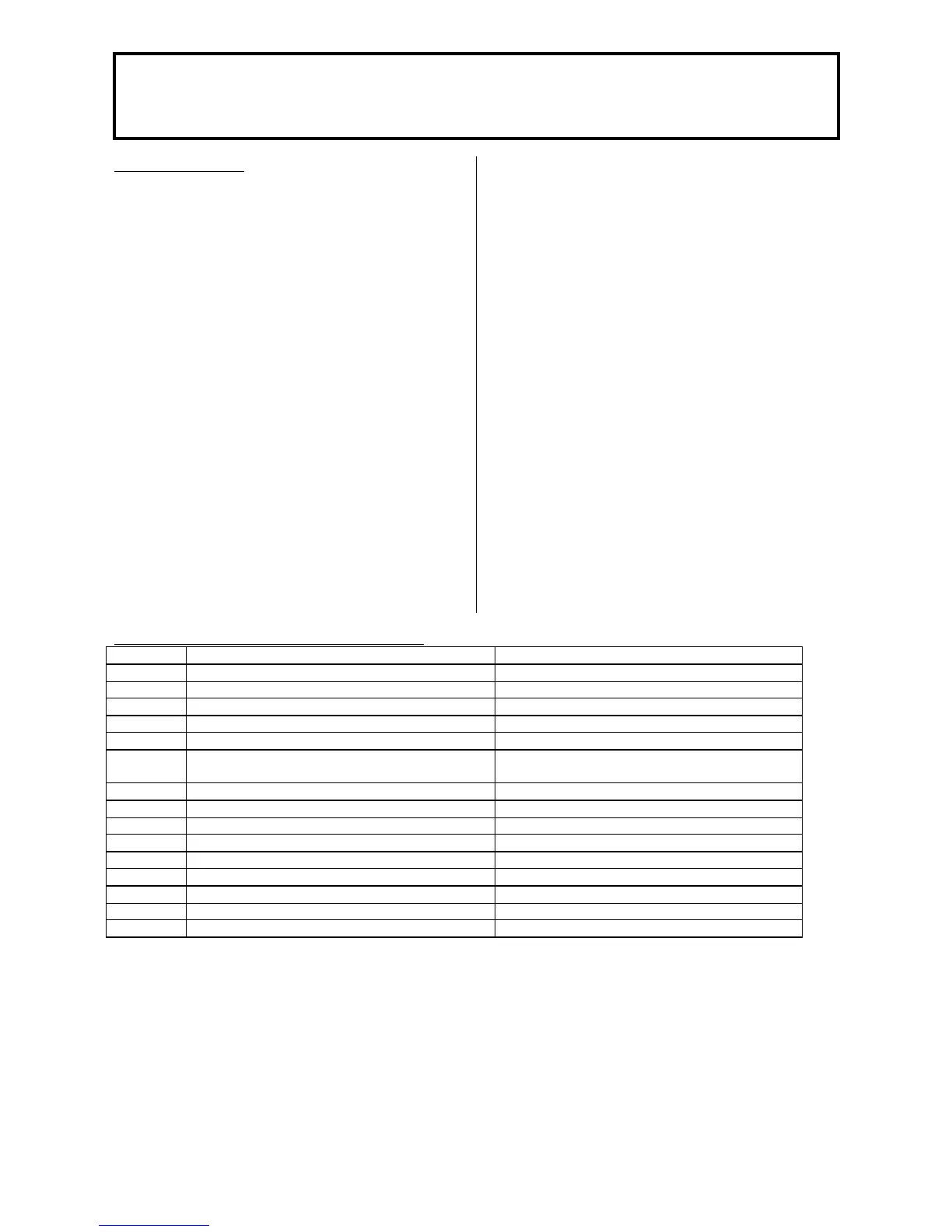
Table 10 Operating Phases of Control Centre
Code “A 4” Operating State Function Description
0 Standby (no heat requirement) Burner on standby
1 Start disable
2 Fan start-up Self-test for burner start and fan start-up
3 Pre-purging time Pre-purging fan deceleration time to starting load speed
4 Waiting time
5 Ignition phase Ignition and start of safety time
Flame formation, ionisation current build up
6 Safety time constant
7 Safety time variable
10 Heating operation Room heating mode, burner in operation
11 Hot water mode Hot-water tank charging, burner in operation
12 Parallel operation for heating and hot water
20 Subsequent ventilation with last operating fan speed Fan continues to run
21 Subsequent ventilation with pre-purging fan speed Fan continues to run
22 Shut down Self-test after controlled shut-down
99 Fault position The current fault code is indicated, see Table 13