Do you have a question about the Potterton Promax Combi 33 HE Plus and is the answer not in the manual?
Explains requirements for installation and commissioning compliance.
Flowchart for notifying authorities about boiler installation.
Critical safety and operational notices for the boiler.
Details legal requirements and standards for boiler installation.
Lists relevant industry standards and codes for installation.
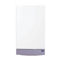
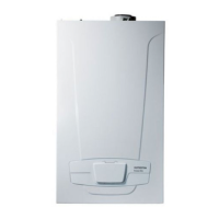
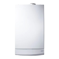
Overview of the Potterton Promax Combi boiler features and models.
Lists items included in the boiler packaging.
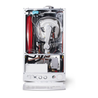
Identifies key components of the boiler with a diagram.
Explains how the boiler functions in central heating mode.
Explains how the boiler functions for hot water.
Describes the boiler's frost protection mechanism.
Provides specifications for different boiler models.
General information on system requirements and approvals.
Details requirements for the central heating system.
Guidance on external controls for system operation.
Steps for filling and pressurising the heating system.
Information on the pressure relief valve and discharge pipe.
Details requirements for the domestic hot water system.
Guidelines for choosing a suitable installation location.
Specifies minimum clearances around the boiler.
Details requirements for the gas supply connection.
Details requirements for the electrical supply connection.
Instructions for installing the condensate drain pipe.
Guidelines for siting the flue terminal.
Details for installing horizontal flue systems.
Details for installing twin and vertical flue systems.
Lists available accessories for flue systems.
Instructions for fitting the flue duct adaptor.
Instructions for fitting the air duct adaptor.
Specific instructions for roof terminal installations.
Guidance on when and how to fit terminal guards.
Details the plume displacement kit and its contents.
How to calculate permissible flue lengths using graphs.
General instructions for fitting the plume displacement system.
Steps for unpacking the boiler and preparing for installation.
Instructions for physically mounting the boiler.
Instructions for connecting the condensate drain.
Details for fitting the horizontal flue.
Further details for fitting the flue, including vertical.
Steps for connecting the boiler's electrical supply.
Checks to perform before commissioning electrical systems.
Steps to commission the boiler after installation.
Details on checking gas rate and other parameters during commissioning.
Final steps after installation and commissioning.
Instructions for performing annual boiler servicing.
Further steps for annual boiler servicing.
Steps for replacing the igniter.
Steps for replacing spark and sensing electrodes.
Steps for replacing the fan assembly.
Steps for replacing the venturi.
Steps for replacing the injector.
Steps for replacing the burner.
Steps for replacing the boiler insulation.
Steps for replacing the flue/heat exchanger thermostat.
Steps for replacing the water pressure sensor.
Steps for replacing the CH temperature sensor.
Steps for replacing the safety thermostat.
Steps for replacing the DHW temperature sensor.
Steps for replacing only the pump head.
Steps for replacing the entire pump assembly.
Steps for replacing the automatic air vent.
Steps for replacing the pressure gauge.
Steps for replacing the Hall Effect sensor.
Steps for replacing the pressure relief valve.
Steps for replacing the plate heat exchanger.
Steps for replacing the diverter valve motor or assembly.
Steps for replacing the printed circuit board (PCB).
Steps for replacing the selector switch.
Steps for replacing the gas valve.
Steps for replacing the expansion vessel.
Procedure for checking and adjusting CO2 levels.
Diagram showing the boiler's electrical connections.
Basic checks to perform before diagnosing faults.
Explains error codes displayed by the boiler.
Flowchart for troubleshooting central heating faults.
Flowchart for troubleshooting hot water faults.
Sections A, B, C, D detailing specific fault diagnoses.
Sections E, F, G, H detailing specific fault diagnoses.
Sections I, J, K, L, M detailing specific fault diagnoses.
| Boiler Type | Combi |
|---|---|
| Output | 33 kW |
| Fuel Type | Natural Gas |
| Efficiency | A Rated |
| Dimensions (HxWxD) | 700 x 400 x 300 mm |
| Weight | 38 kg |
| Hot Water Flow Rate | 13.5 l/min |
| Mounting | Wall-mounted |
| ERP Rating | A |
| Domestic Hot Water Output | 33kW |
| Central Heating Output | 33 kW |
| Water Pressure | 3 bar |