4.1.4. Errors referred to the configuration
The user diagnostics area starts at the offset byte 6. Bytes 0 through
5 are reserved for the standard diagnostics information as follows:
Byte 0 – Station Status_1
Byte 1 – Station Status_2
Byte 2 – Station Status_3
Byte 3 – Diag.Master_Add
Byte 4 – Ident_Number_High
Byte 5 – Ident_Number_Low
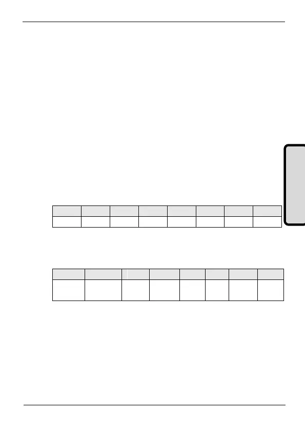
The extended diagnostics information is 12 bytes long (including the
size field) and starts at Byte offset 6.
Byte 6: Length of the Buffer
Size of the extended diagnostics information including this byte.
Fixed at 0x0C (12).
Byte 7 - Bit encoded for several errors.
The bits are set if the corresponding error prevails.
o BIT 0 = Err. WR REG. NUMBER
This BIT can be set for the following error conditions:
a) The number of the registers configured for writing operation in
the write scenarios exceeds the limit specified by the
configuration type.