Rev. J 08/16
20
TOP252-262
www.power.com
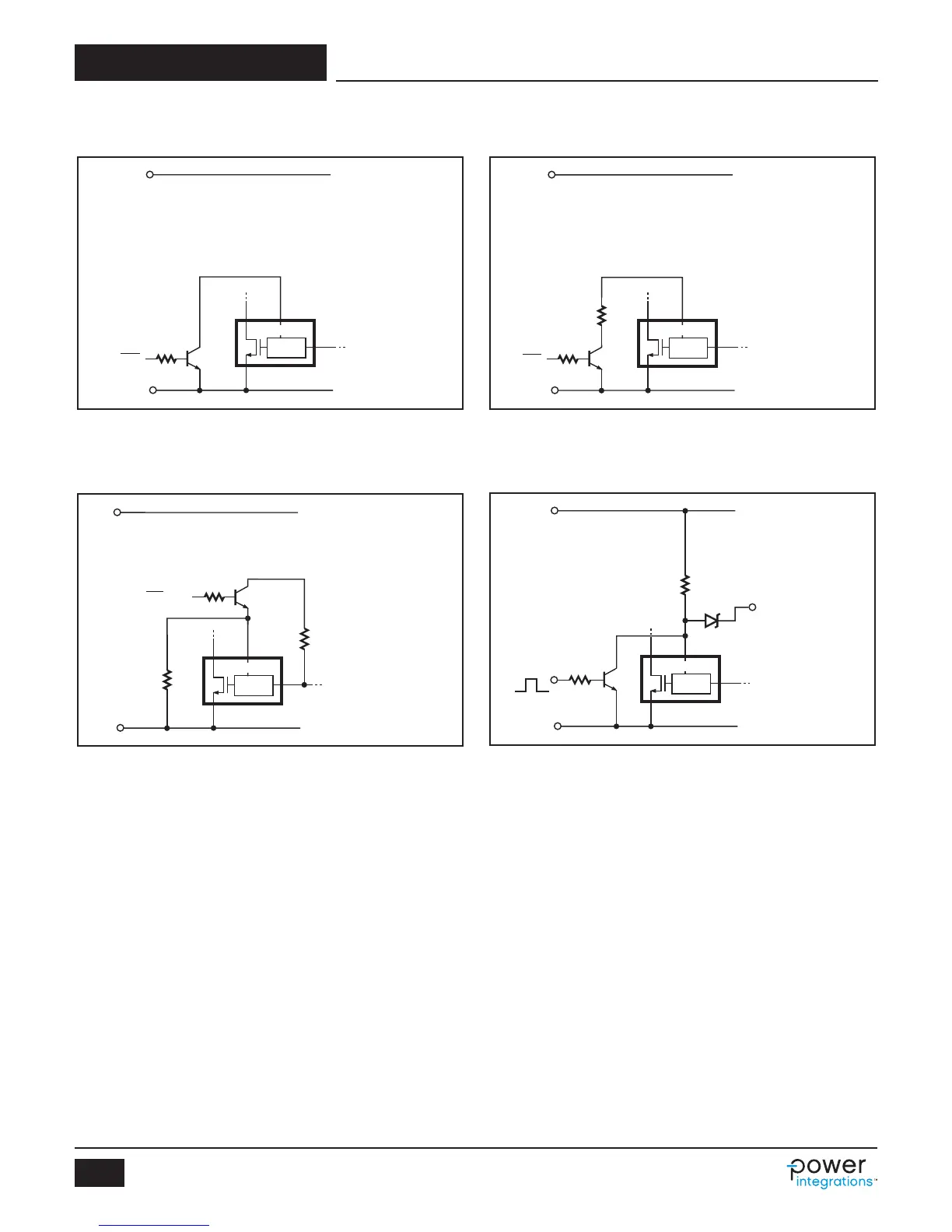
Typical Uses of MULTI-FUNCTION (M) Pin (cont.)
PI-4757-120307
DC
Input
Voltage
Sense Output Voltage
+
-
D M
S
C
V
UV
= I
UV
× R
LS
+
V
M
(I
M
= I
UV
)
V
OV
=
I
OV
×
R
LS
+
V
M
(I
M
= I
OV
)
For R
LS
= 4 MΩ
V
UV
= 102.8 VDC
V
OV
=
451 VDC
DC
MAX
@ 100 VDC = 76%
DC
MAX
@ 375 VDC = 41%
CONTROL
R
LS
4 MΩ
10 kΩ
Q
R
Reset
Figure 40. Line-Sensing for Undervoltage, Overvoltage, Line Feed-Forward and
Latched Output Overvoltage Protection with Device Reset.
PI-4736-060607
DC
Input
Voltage
+
-
D
S
C
R
IL
R
MC
24 kΩ
12 kΩ
M
CONTROL
Q
R
2R
IL
R
MC
=
Q
R
can be an optocoupler
output or can be replaced
by a manual switch.
ON/OFF
7 kΩ
Figure 39. Active-off Remote ON/OFF with Externally Set Current Limit
(see M Pin Operation Description).
PI-4735-092107
DC
Input
Voltage
+
-
D
S
C
Q
R
R
IL
M
CONTROL
12 kΩ
For R
IL
=
I
LIMIT
= 61%
Q
R
can be an optocoupler
output or can be replaced
by a manual switch.
ON/OFF
16 kΩ
19 kΩ
For R
IL
=
I
LIMIT
= 37%
Figure 38. Active-on Remote ON/OFF with Externally Set Current Limit
(see M Pin Operation Description).
PI-2519-040501
DC
Input
Voltage
+
-
D
S
C
Q
R
ON/OFF
M
CONTROL
Q
R
can be an optocoupler
output or can be replaced
by a manual switch.
47 kΩ
Figure 37. Active-on (Fail Safe) Remote ON/OFF.
 Loading...