30
1
Socket meter only.
Optional IRIG-B GPS Time Synchronization
IRIG-B cannot be configured via the meter’s front panel. See the
IRIG-B Product Option document for configuration procedures.
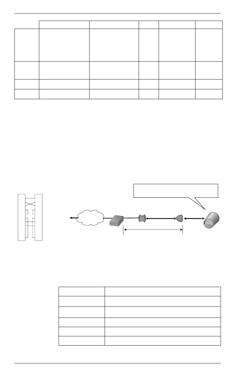
External Modem Connections
Connect COM 1 (RS-232) to a remote modem connected to a PC. Use a null-
modem RS-232 cable to connect meter to an external modem One end of
the cable must be equipped with a Micro-Fit 3.0 Molex female connector for
mating with the meter’s Molex male connector.
Use an RS-232 to RS-485 converter (such as COM32 or COM128) to
connect multiple meter COM1 ports (selected as RS-485) to remote modem.
Step 6: Wire the Power Supply
Fibre
1
z
Available with
Onboard I/O
provided no
Outage
Dialback is
present.
EtherGate
z
z
Not available if internal
modem option on this
port
Internal
Modem
z
Modem-
Gate
z
COM 1 COM 2 COM 3 Network IRIG-B
Attach the Molex connector from the meter
to a break-out cable or the I/O Expander
50 feet (15.2 m) max
null
modem
to workstation
modem
RS-232
COM 1
remote
modem
Telephone
Network
DB9 female
1
2
3
4
5
6
7
8
20
1
2
3
4
5
6
7
8
20
DB25 Null Modem
Wiring Diagram
Type Captured wire connector
Wire
3.3 to 2.1 mm
2
(12 to 14 AWG)
Rated Inputs
85-240 VAC ±10%
(47-63 Hz), or 110-330 VDC ±10%
Dielectric Withstand 2500 VAC RMS, 60 Hz for 60 s
Burden 20 VA max. (10 VA typical)
Ride-through 100 ms (6 cycles @ 60 Hz) min.
 Loading...