2. Use the (1) heat shrink butt connector (D) to connect the red wire to the red fuse holder
wire and crimp.
3. Use the (1) heat shrink ring terminal connector (E) to connect to the black wire and crimp.
4. Connect the red fuse holder ring terminal to the main battery cut-off switch and
the black ring terminal to the negative post on the cranking battery. The LED light
on the top of the MICRO Driver Unit will begin fl ashing green.
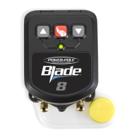
Connecting the Driver Unit to Power Source
Using a 12 volt DC battery
1. Plug the male plug connector into the
MICRO Driver Unit and route wires
through the boat to power source.
Male plug connection dust cover
NOTICE: Keep male plug
connection cover on when not
plugged into MICRO Driver Unit
MICRO Driver Unit
Female plug connection
H
I – Fuse Holder
H – Power Cord End
D
E
 Loading...