www.powerbox-systems.com 5
Note regarding home-assembled battery packs: connecting a battery to the
unit with reversed polarity will immediately destroy the internal linear regulators!
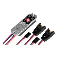
The backer’s outputs can be connected differently depending on the type of recei-
ver used. The outputs of the Sensor V3 are present as two-core and three-core
leads. For all systems except the CORE the two outputs can be considered to be
identical.
If your receiver only has one battery input, simply connect one of the Sensor V3’s
outputs to the receiver’s battery input, and the other to any vacant servo output
socket. If there is no servo output available, a Y-lead can be connected to a servo
output socket, to which the Sensor V3 and the servo are connected.
If you are using CORE receivers please note that the three-core lead must be
connected to the receiver’s P²BUS input, otherwise the battery telemetry data will
not be sent to the transmitter.
Important: always connect the two-core lead to a vacant servo output - not the
Fasttrack output! The power supply lead from the P²BUS and Fasttrack connec-
tors to the connected servos may not be sufcient for all the servos connected
to the system!