www.powerbox-systems.com 7
80 – 100 % 60 – 80 % 40 – 60 % 20 – 40 % 0 – 20 %
Note regarding the LED display: the battery indicators do not follow battery voltage
in a linear fashion. We have tested and measured various currently available bat-
tery types, and produced an average discharge curve from this information; this
discharge curve is used as the basis for a percentage indication of battery state.
The LED indicators correspond to the battery status as follows:
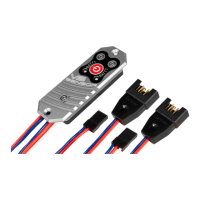
5. SETTING THE OUTPUT VOLTAGE
The PowerBox Sensor V3 can be set to either of two output voltages: 6.0 V for
conventional servos, and 7.8 V for HV servos. If you opt for the higher setting,
please ensure that all the components connected to the system are approved for
high-voltage use.
The advantage of regulating the voltage at 7.8 V, instead of simply allowing the
full battery voltage to pass through, is that it suppresses the high battery voltage
present just after charging. The voltage remains stable right from the outset, which
means that servo speed and power are constant for a longer period.
If you wish to change the output voltage, hold the button pressed in while you
connect one of the batteries. The LED will initially light up green, then switch to red
after three seconds. Release the button when the colour is correct for your required
output voltage: green = 6.0 V, red = 7.8 V.
The LED now ashes white to conrm that the set-up process is complete.
Repeat the exact procedure with the second battery connection.