www.modellmarkt24.ch
4 PowerBox-Systems − World Leaders in RC Power Supply Systems
3. FIRST STEPS BEFORE USING THE UNIT
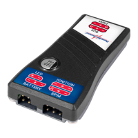
3.1. CONNECTIONS
connect the battery.
For safety reasons it is absolutely essential to connect the external LED. The exter-
nal LED must be installed in a position where the pilot can clearly see it at all times
when starting the engine.
Caution: if you do not install the external LED, the pilot will be unable to check the
switched status of the ignition, and this involves unnecessary hazards.
3.2. IGNITION BATTERY
All types of ignition battery can be used: i.e. 2S LiPo, 2S LiFePo, 5S NiCd or NiMH.
Regardless of battery, the integral regulator always limits the voltage to 5.9 V, which
means that the SparkSwitch can be used with all ignition units such as 4.8 V, 6.0
V and 7.4 V types.
The ignition battery can be left connected to the SparkSwitch permanently. When
switched off, the unit draws such a low current (only 0.2
μμA!) that it will not dischar-
ge the battery - even over a period of months or years.
3.3. SETTING UP THE TRANSMITTER
There are two methods of switching the unit on, according to the transmitter set-
up. Please note: 0% means servo centre, -100% and +100% means the two servo
www.modellmarkt24.ch