Do you have a question about the Powerline PCH-24X and is the answer not in the manual?
Critical safety rules and warnings for using the equipment to minimize risk and prevent injury.
Specific guidance on inspecting and maintaining cables to prevent breakage and ensure safe workouts.
Essential safety rules to follow when using the exercise equipment to minimize risks.
Guidelines for ensuring personal safety during the assembly process of the equipment.
Information on how to get service, order parts, and contact customer support.
Lists the basic tools necessary for assembling the PCH-24X exercise machine.
Specifies installation conditions, space, surface requirements, and helpful assembly advice.
Details the information needed when contacting for replacement parts.
A comprehensive list of all hardware parts with their respective quantities for assembly.
Visual representation and identification of all hardware parts with their sizes and quantities.
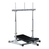
Identifies major machine components by letter (A-H) with their names and quantities.
Instructions for attaching base frames (B) to the mainframe (A) and inserting foot caps.
Instructions for attaching the mid-support frame (F) and side frames (D, E) to the mainframe (A).
Instructions for attaching the grip frame (C), support pads (H), end caps, and rubber grips.
Instructions for inserting end caps, bushings, the roller adjuster (G), and foam rollers.
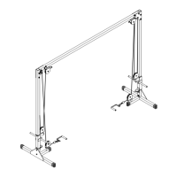
A detailed visual representation showing all parts and their connections in an exploded format.
Space provided to record the machine's serial number for future reference and warranty.
Official contact information for Body-Solid, including address, phone, and fax for support.
| Stations | 1 |
|---|---|
| Type | Home Gym |
| Material | Steel |
| Pull-up Bar | Yes |
| J-Hooks | Yes |