4 Owner’s Manual for Portable Generator
Section 2 General Information and Setup
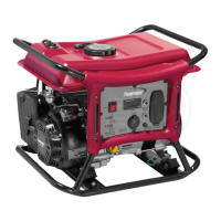
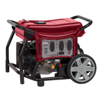
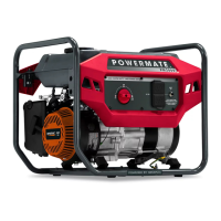
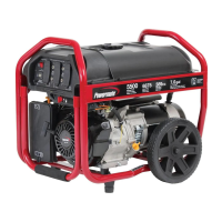
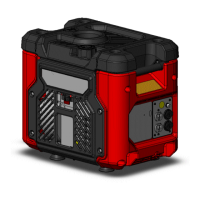
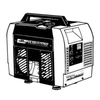
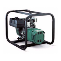
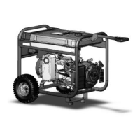
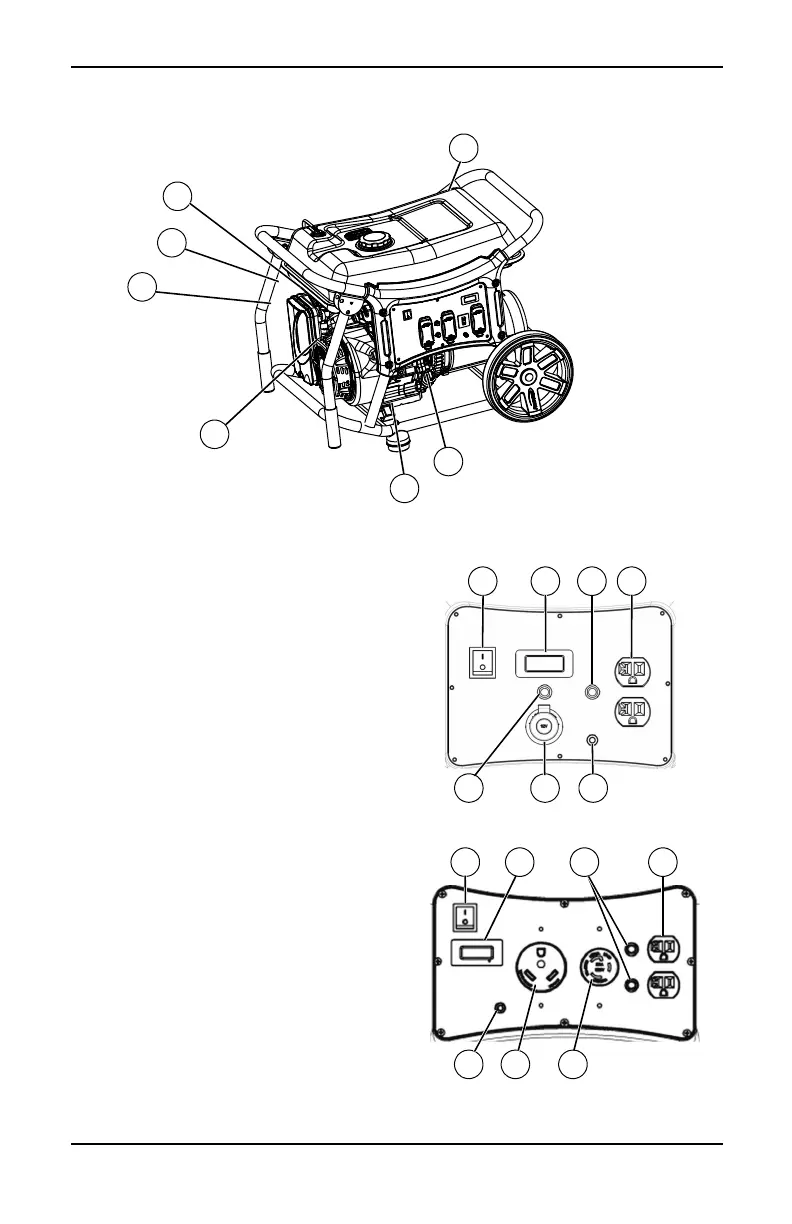
Figure 2-1. Features and Controls
TABLE 1. Generator Components
Figure 2-2. CX1400 Control Panel
Figure 2-3. CX3500 Control Panel (CSA/CARB)
1 120 Volt AC, 20 Amp Duplex Receptacle
2 120/240 Volt AC, 30 Amp Locking
Receptacle (NEMA L14-30R)
3 Circuit Breakers (AC)
4 On/Off Switch
5 Hour Meter
6 Ground Terminal
7 Choke Lever
8 Fuel Tank
9Oil Drain
10 Oil Fill
11 Air Cleaner
12 Recoil Handle
13 Fuel Shutoff Valve
14 Battery Charger
15 Circuit Breaker (DC)
16 120 Volt AC, 30 Amp Locking Receptacle
(NEMA L5-30R)
17 120 Volt AC, 30 Amp Receptacle (NEMA
TT-30R)
18 2-pole Circuit Breaker (AC)
19 120 Volt AC, 20A GFCI Duplex
Receptacle (CX5500 CARB only)
002340