P84905-001 A Sheet 12 of 36
Control PC Board
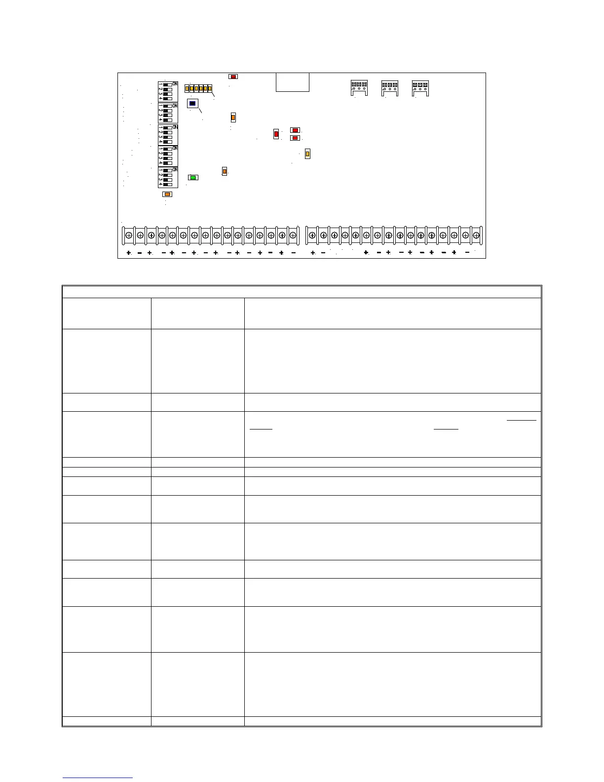
Refer to Figure 4 for the locations of the terminal described in Table 3.
IN1 IN2
CC1 CC2
SBUS
IN
SBUS
RET
SIL
IN
RET1
RET2
COM
NO
NC
TROUBLE
AUX
OUT
NAC1
OUT
NAC2
OUT
NAC3
OUT
NAC4
OUT
TB1
TB2
TB6
TB3
TB4
SW2
SW1
SW3
SW4
IN2 FOLLOWER OFF/ON
TROUBLE LATCH OFF/ON
SBUS IN1/IN2
GF DETECT ON/OFF
SBUS SYNC/TEMPORAL
SYNC PROTOCOL
SYNC PROTOCOL
NAC1-NAC2 CLASS A/B
NAC3-NAC4 CLASS A/B
AUX POWER CP/MP
SBUS MASTER/REMOTE
NAC4 SYNC/TEMPORAL
NAC4 IN1/IN2
NAC3 IN1/IN2
NAC2 IN1/IN2
NAC1 IN1/IN2
IN1 FOLLOWER OFF/ON
SW6
NAC3 SYNC/TEMPORAL
NAC2 SYNC/TEMPORAL
NAC1 SYNC/TEMPORAL
D30
IN2
D31
D36
INPUT1
INPUT2
D38
SILENCE
D2
GENERAL TROUBLE
D37
ACTIVE
SW5
D40
D3: GROUND FAULT TROUBLE
D4-D8: SEE
TABLE 9
< D8-D4 >
SYNC BUS
GROUND FAULT
LOCATOR
D9
POWER
D1
IN1 TROUBLE
X
Figure 8: Control PC Board
Table 2: Control PC Board Terminal Identification
Terminal Block
Identification
Numbers
Terminal
Identification
Function/Description
TB1-1, 2
IN1+, IN1- These terminals connect to the input voltage source (i.e. 12VDC or 24VDC
FACP). The FACP will supply a voltage from 8-33VDC at 5mA. During the alarm
condition these inputs will cause the designated outputs to drive the notification
appliances (designated outputs are set by output DIP switch banks). During
Stand-by on a FACP, a trouble condition on the designated loop will cause these
inputs to open, providing a trouble condition on the FACP. Alarm condition always
overrides trouble to drive output indicating appliances.
TB1-3, 4,
RET1+, RET1- EOLR is connected on these terminals corresponding to IN1+ and IN1-, or the
loop may be continued to other power supplies or appliances before terminating.
TB1-5, 6
CC1+, CC1- Dry contacts are used to actuate the designated outputs. Contacts are normally
closed and actuate the power supply on contact OPEN. Designated outputs
correspond to IN1+, IN1-. NOTE: FACP NAC circuit cannot energize the power
supply by these contacts. When these terminals are not in use, a jumper must be
connected across them.
TB1-7, 8
IN2+, IN2- Same as IN1+, IN1- for corresponding terminals.
TB1-9, 10
RET2+, RET2- Same as RET1+, RET1- for corresponding terminals.
TB1-11, 12
CC2+, CC2- Operates the same as C “Dry2” NC for corresponding terminals. When these
terminals are not in use, a jumper must be connected across them.
TB1-13, 14
S BUS IN+, IN- Synchronizing Bus IN: Links from previous PS-8 (PS-6) “S BUS RET” to
synchronize both together. Controlled as Master or Remote by switch SW3
Position 4. Current Draw is 0.006 Amps per PS-8 (PS-6).
TB1-15, 16
S BUS RET+, RET- Synchronizing Bus RET: Sync control output from the master PS-8 (PS-6) to
additional PS-8 (PS-6) panel “S BUS IN” terminals. Always place 10K Ohm
EOLR on the last panel. Controlled as Master or Remote by switch SW3 Position
4. Up to 40 power supplies can be connected to the PS-8 or 12 to the PS-6.
TB2-1,2
SIL+, SIL- Audible Silence: NAC input to the master PS-8 (PS-6) from FACP. The Audible
signal is transmitted to all PS-8 (PS-6) panels within the loop. Power Limited.
TB2-3,4,5
“NO” “C” “NC”
(COMMON TROUBLE
OUTPUT)
Typically used to trigger remote alerts or other reporting appliances. Form “C”
contacts rated 24VDC at 1 Amp. NOTE: These terminals must be monitored by
the FACP for Class “A” mode.
TB2-6, 7
+ AUX OUT - This output has two modes of operation. The CP Mode is capable of 0.02 Amps
for 60 hours (PS-8 only) or 0.24 Amps (PS-8)/0.075 Amps (PS-6) for 24 hours on
battery back up for desired auxiliary equipment. The MP Mode provides up to 2.5
Amps in non-alarm condition or when the input AC is present. Special
Applications, Power Limited.
TB2-8, 9
TB2-10, 11
TB2-12, 13
TB2-14, 15
+OUT1-
+OUT2-
+OUT3-
+OUT4-
NAC appliances are connected to these outputs. Each output can supply a
maximum load of 3.0 Amps, Class "B" or 3.0 Amps Class "A" and can be
individually programmed for Wheelock Strobe Sync Mode, Temporal Mode or
Input follower Mode. The outputs can be configured as four Class "B" circuits,
two Class "A" circuits, or two Class "B" and one Class "A" circuits. Outputs are
controlled by a designated input (INPUT 1 or 2) as selected by the DIP switch for
that output. Power Limited.
TB2-16
Not Used