P84905-001 A Sheet 17 of 36
BATTERY MAINTENANCE
Battery Replacement: Replace with new batteries every four (4) years or as needed if battery will no longer accept full
charge. Two 12V batteries are required for 24VDC.
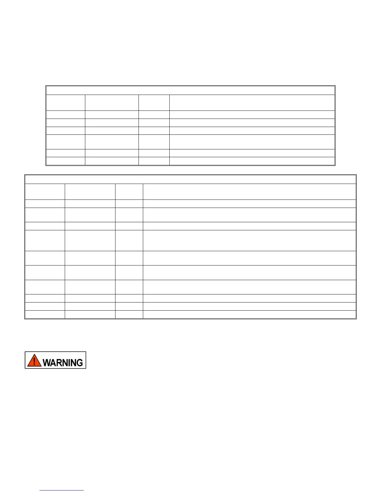
The Power supply is now operational. Table 5 is a list of the LED indicators on the Power Supply/Battery Charger PC
board. Table 6 is a list of the LED indicators on the Control PC board. Amber LED indicators always indicate a trouble
condition. If amber LED indicator(s) light turn to the troubleshooting section for resolution.
Table 4: Power Supply/Battery Charger PC Board LED Identification
LED
Designator
Identification
LED
Color
Description
D38 AC Power Green Indicates when AC power is applied to the PC board.
D24 Battery Power Green Indicates when battery power is applied to the PC board.
D34 Battery Trouble Amber Indicates that a trouble condition exists on the battery circuit.
D35 Battery Charger
Trouble
Amber Indicates that the battery charger section is not working.
D36 Processor Trouble Amber Indicates that a trouble condition exists on the processor circuit.
D21 AC Loss Amber Indicates a brown out or total loss of AC power.
Table 5: Control PC Board LED Identification
LED
Designator
Identification
LED
Color
Description
D9 Power Green Indicates when power is applied to the Control board.
D37 Active Red Indicates when the power supply is activated and supplying power to the NAC
output circuits.
D2 System Trouble Amber Indicates that a general trouble condition exists on the Control board.
D8, D7, D6,
D5, D4
Coded Trouble
LEDs
Amber These five LEDs light in a coded pattern indicating the location and type of trouble
condition. If multiple troubles are present the LEDs will indicate the highest priority
trouble. When repaired the LEDs will indicate the next priority trouble.
D3 General Ground
Fault
Amber Indicates that a ground fault condition exists. Pressing switch SW5 will cause the
code pattern on the coded Trouble LEDs to locate the location.
D1, D30 IN1 RET, IN2
RET Trouble
Amber Indicates that a general trouble condition exists, and the IN1 RET and IN2 RET
relays are open.
D40 SYNC BUS
Power Active
Green This LED lights when 24V is present on the SYNC BUS.
D31 IN1/CC1 Active Red This LED lights when IN1 or CC1 has been activated.
D36 IN2/CC2 Active Red This LED lights when IN2 or CC2 has been activated.
D38 Silence Active Red This LED turns on when the “SILENCE” feature has been activated.
5.0 TROUBLESHOOTING:
THE PS-8 POWERPATH CONTAINS VOLTAGES THAT CAN CAUSE DEATH OR SERIOUS
INJURY. ALWAYS OBSERVE PROPER ELECTRICAL SAFETY PRECAUTIONS AND
WARNINGS.
Always follow good troubleshooting procedures:
• When trouble occurs, observe all visual indications and note them Refer to the interior door label.
• If the problem is obvious or it can be located on the Troubleshooting Table, note it. Refer to the interior door label.
• Always de-energize the POWERPATH completely (Remove both AC and DC power) before repairs.
• While the POWERPATH is de-energized, perform a visual and hands on check of all terminals and wires to ensure
proper termination.
• If intermittent troubles occur, use the trouble latch (SW2 Position 4) to find it.