P84905-001 A Sheet 5 of 36
1.3 TERMINOLOGY
CLASS “A” = STYLE Z
CLASS “B” = STYLE Y
FACP = Fire Alarm Control Panel
EOLR = End of Line Resistor
NAC = Notification Appliance Circuit
SM = Wheelock Sync Module with single output
DSM = Wheelock Dual Sync Module with two outputs
C = Common
NC = Normally Closed
NO = Normally Open
Ahrs = Ampere/Hours
Enclosures
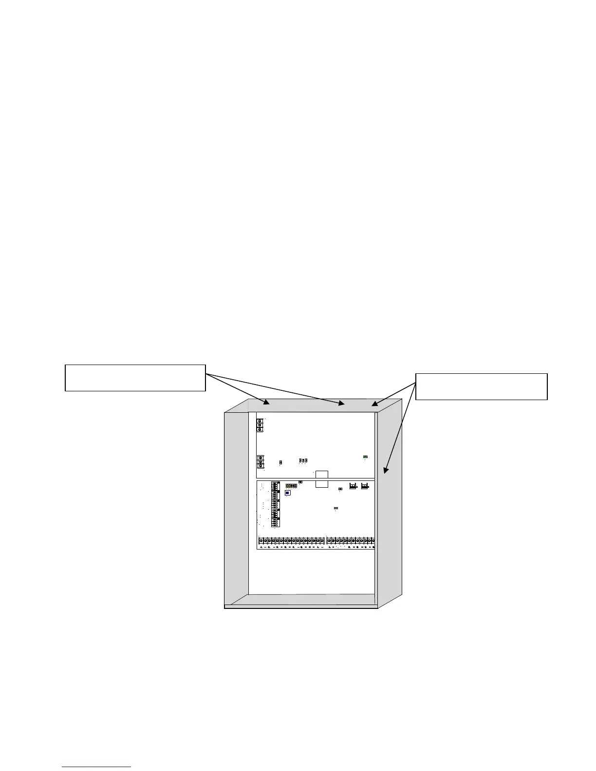
Figure 1 shows the location of the PC boards and knockouts on the PS-8 panel.
IN1 IN2CC1 CC2
SBUS
IN
SBUS
RET
SIL
INRET1 RET2
COM NONC
TROUBLE
AUX
OUT
NAC1
OUT
NAC2
OUT
NAC3
OUT
TB1 TB2
TB3
TB2
TB1
J2
D2
D9
D37
D3D4
D5D6D7D8
D36 D35 D34
D21
D24
SW5
SW2
SW1
SW3
SW4
SW6
IN1 FOLLOWER
IN2 FOLLOWER
TROUBLE LATCH
SBUS IN1/IN2
GF DETECT
SBUS SYNC/TEMPORAL
SYNC PROTOCOL
SYNC PROTOCOL
NAC1-NAC2 CLASS B/A
NAC3-NAC4 CLASS B/A
AUX POWER CP/MP
SBUS MASTER/REMOTE
NAC1 SYNC/TEMPORAL
NAC2 SYNC/TEMPORAL
NAC3 SYNC/TEMPORAL
NAC4 SYNC/TEMPORAL
NAC1 IN1/IN2
NAC2 IN1/IN2
NAC3 IN1/IN2
NAC4 IN1/IN2
Figure 1: PS-8 Enclosure Layout
Figure 2 shows the location of the PC boards and knockouts on the PS-8 panel.
Power Supply/Battery
Charger PC Board
Control PC Board
Battery Compartment for
two – 12V 12Ahrs
Rechargeable Batteries
1/2” and 3/4" Knockouts (14)
2”, 2 ½”, and 3” Knockouts (2)