P84905-001 A Sheet 14 of 36
3.0 SETTING THE DIP SWITCHES
3.1 CONTROL PC BOARD
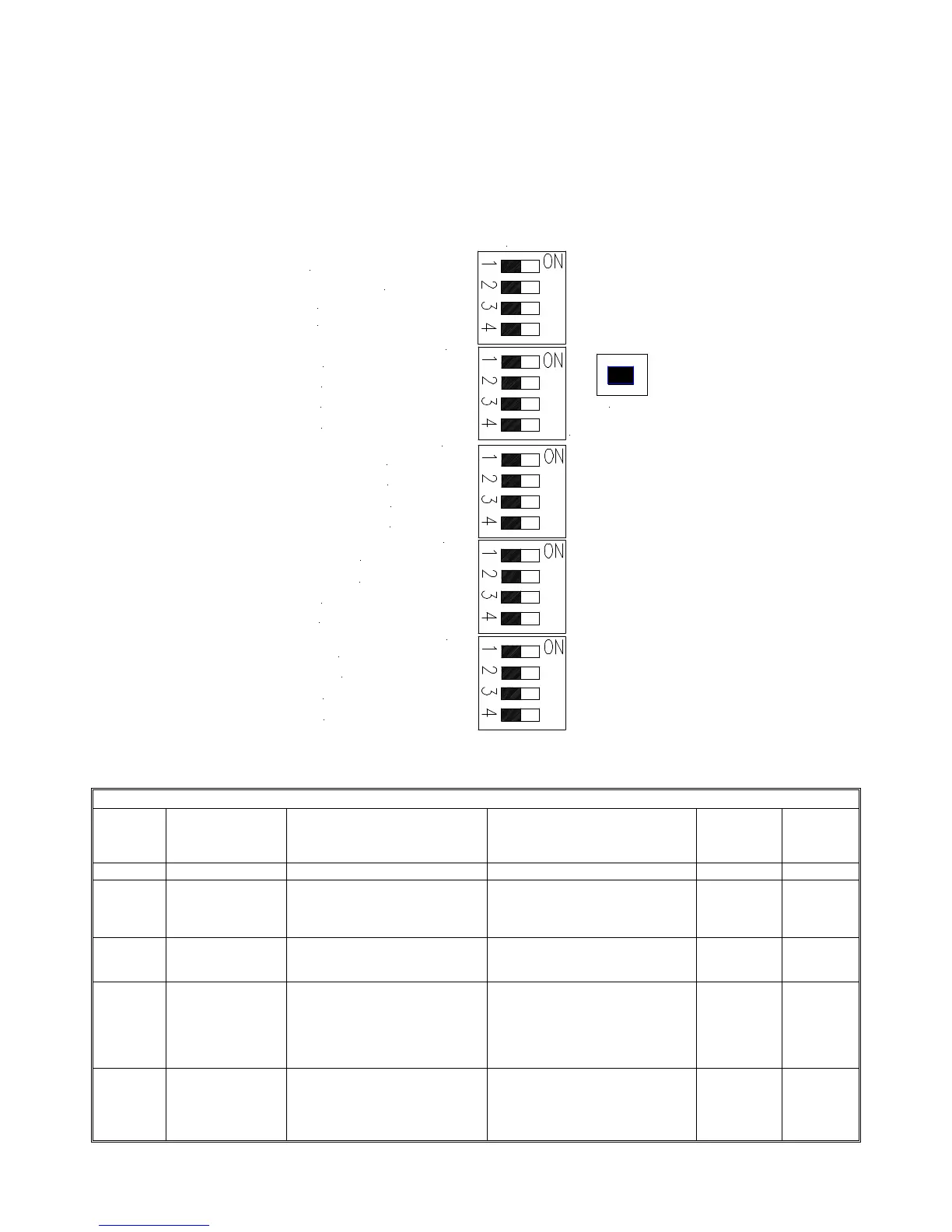
Refer to Figure 9 for the location and setting of the DIP switches on the Control PC board.
1. Set NAC output DIP Switch(s) on SW1 to follow corresponding input (IN1, IN2).
2. See Figure 8 for DIP switch locations and Table 3 for DIP Switch Selection and DIP Switch Settings
SW5
SW2
SW1
SW3
SW4
IN2 FOLLOWER OFF/ON
TROUBLE LATCH OFF/ON
SBUS IN1/IN2
GF DETECT ON/OFF
SBUS SYNC/TEMPORAL
SYNC PROTOCOL
SYNC PROTOCOL
NAC1-NAC2 CLASS A/B
NAC3-NAC4 CLASS A/B
AUX POWER CP/MP
SBUS MASTER/REMOTE
NAC4 SYNC/TEMPORAL
NAC4 IN1/IN2
NAC3 IN1/IN2
NAC2 IN1/IN2
NAC1 IN1/IN2
IN1 FOLLOWER OFF/ON
SW6
NAC3 SYNC/TEMPORAL
NAC2 SYNC/TEMPORAL
NAC1 SYNC/TEMPORAL
GROUND FAULT TEST
LOCATOR SWITCH
Figure 9: Control PC Board DIP Switches
Table 3: Control PC Board DIP Switch Settings
DIP
Switch
Function
Description
OFF or “0”
ON or “1”
Used in
MASTER
Mode
Used in
REMOTE
Mode
SW6
Position 1 TROUBLE LATCH
OFF/ON
Trouble conditions clear
automatically as condition is
repaired.
Trouble indicators latch ON until
this switch is switched to the
disable position or all power is
removed from the panel.
X
X
Position 2 SBUS IN1/IN2 If the SYNC BUS detects a
trouble condition, it will break the
IN1_RET connection.
If the SYNC BUS detects a trouble
condition, it will break the IN2_RET
connection.
X
Position 3 IN2 FOLLOWER
OFF/ON
NAC Output(s) or SBUS set to
trigger on IN2 or CC2 will
generate signals according to its
SYNC/TEMPORAL switch setting.
NOTE: This switch is ONLY used
in the SBUS MASTER mode.
NAC Output(s) or SBUS set to
trigger on IN2 or CC2 turn on when
IN2 or CC2 is “Active” and supplies
NAC reverse supervision voltage
when IN2 or CC2 is “Not Active”
X
X
Position 4 IN1 FOLLOWER
OFF/ON
NAC Output(s) or SBUS set to
trigger on IN1 or CC1 will
generate signals according to its
SYNC/TEMPORAL switch setting.
NAC Output(s) or SBUS set to
trigger on IN1 or CC1 is “Active”
and supplies NAC reverse
supervision voltage when IN1 or
CC1 is “Not Active”
X
X