MODEL P2201 CAT. NO.52006/Deluxe Kit 52007/Blister Pack
8 P2201
Proper Maintenance and
Cleaning
MAKE SURE THE TOOL IS NOT LOADED. BE SURE
THE TOOL IS NOT HOT PRIOR TO ATTEMPTING
DISASSEMBLY OR CLEANING.
DAILY FUNCTION TEST
Check the functioning of the tool, without a powder load or
fastener in the tool, by pushing down against the work surface,
pulling the trigger, and releasing the tool from the work surface.
Function the unloaded tool several times and insure that the
breech parts and firing mechanism operate freely before
fastening with the tool.
Your Powers Fasteners Authorized representative should be
asked to assist the first time you disassemble and
clean your tool.
If you ever have any trouble reassembling the tool, or have
any doubt about worn parts, call your Powers Fasteners
Authorized Powder Distributor.
CLEANING
AIl parts should be cleaned with detergent oil and the wire
brushes supplied with your tool kit. Remove heavy dirt build-up
with the brush. After cleaning with oil, all parts should be wiped
thoroughly dry. Excess oil will tend to collect dirt and dust. Wear
eye protection when cleaning the tool.
The piston rod, barrel assembly, and receiver should all be
cleaned of excess dirt on a daily basis. Check the condition of
the piston for damage to the piston for wear and deformation.
To maintain this tool in good working condition, it is
necessary to disas semble and clean the entire tool if dirt is evident
in the breech face, or if the tool appears to lose power. All parts
should be cleaned with oil and wire brushes. Remove heavy dirt.
All parts should be wiped thoroughly dry after cleaning with oil.
General tool mainte nance should be performed at six month
intervals or more frequently as required by the frequency of tool use.
REPLACING OR REPAIRING THE PISTON
The piston is an expendable part and must be replaced
periodically. Typical signs of a worn out
piston are: breaking, bending or
mushrooming. Prior to servicing the tool
make sure there is no powder load in the
tool. Use caution and do not lose or
damage any tool parts.
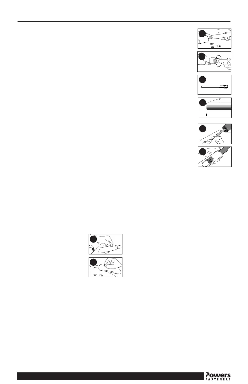
1. Loosen the cap on the reset pin by
turning it counter clockwise. Remove the
reset pin cap.
2. Hold the barrel in place, then remove the reset pin spring and
reset pin.
3. Slide the barrel from the receiver by
pulling it forward. If excessive dirt is built up
inside the receiver, clean it with a wire brush.
4. Unthread the nose piece from the barrel
by turning it counter clockwise. Pull the
piston forward out of the barrel.
NOTE: If a vise clamp is used to hold the
barrel, protect the bar rel from damage.
5. Clean the piston using a wire brush.
Inspect it for worn or damaged piston ring,
chipped end, or bending. Apply lubricant to the
piston shank to minimize piston sticking from
an overdrive con dition. Wipe the piston dry.
6. If a piston tip is damaged, it can be
shortened a maximum of 0.20 inches. The
tip of the piston
should be grooved flat and at 90 degrees to
the shank of the piston. The cham fer of the
piston must also be reground as
shown. Piston grinding should be performed
by qualified per sonnel using the proper
equipment.
REASSEMBLY:
7. Press the piston into the barrel. Thread
the nose piece into the barrel and tighten it
clockwise until finger tight. Be sure the nose
piece is fully seated.
8. Align the slot in the barrel with the reset pin opening in the
bottom of the receiver. Insert the barrel into the receiver. Insert
the reset pin, and reset pin spring. Tighten the reset pin cap
clockwise until it is finger tight and fully seated.
Upon reassembly of the tool perform the following test.
Depress the tool against a flat, hard surface and pull the trigger.
The barrel assembly should slide smoothly inside the tool receiver.
The firing pin should release after the trigger has been pulled.
CAUTION: THIS TEST SHOULD BE PERFORMED
WITHOUT A PIN OR POWDER LOAD IN THE TOOL.
1
2
3
4
5
6
7
8
 Loading...