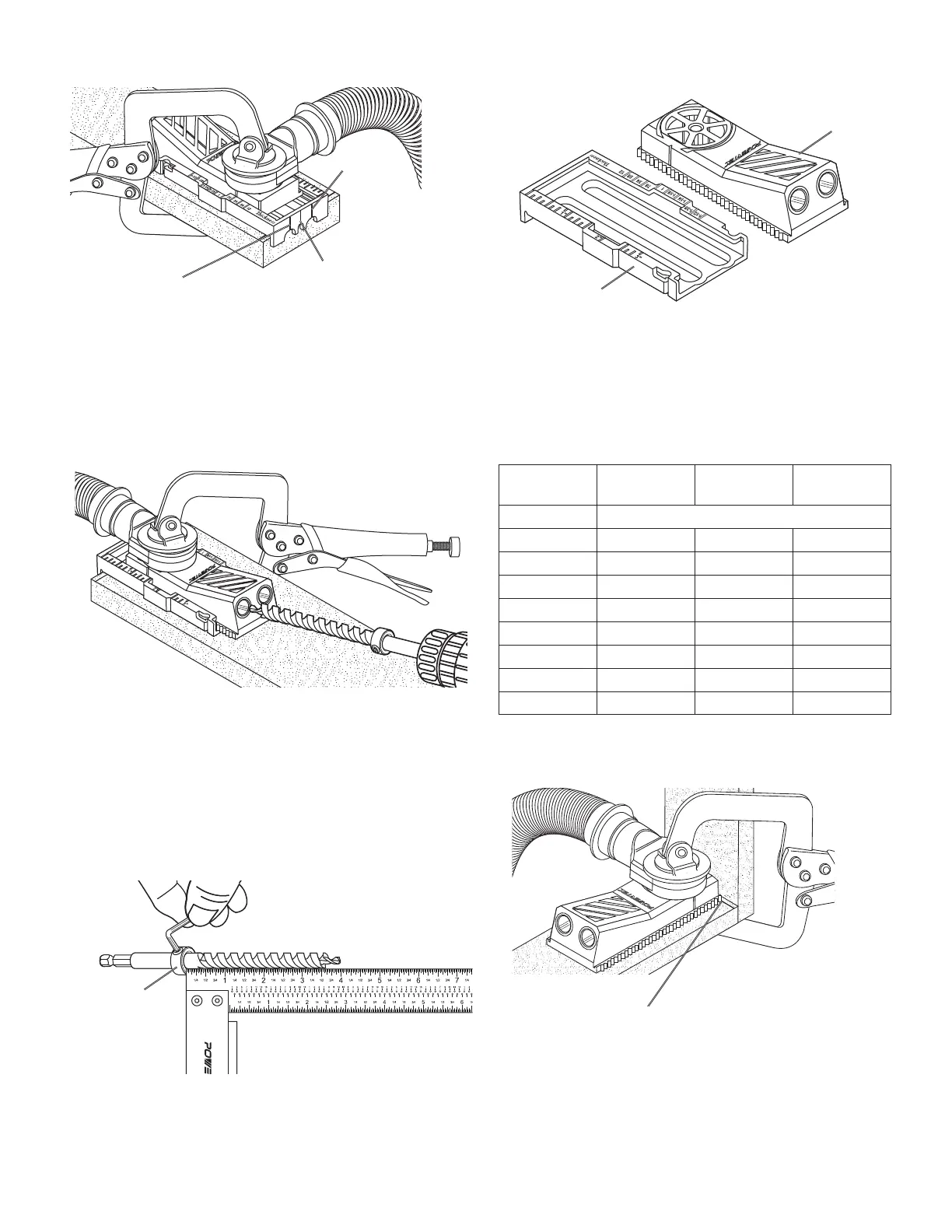
Figure 5
The center
between the
two holes to be
drilled
The center of
the hole to be
drilled
The center of
the hole to be
drilled
NOTE: When drilling two holes, align the central line on the jig
with the mark.
NOTE: When drilling single holes, align one of the two outside
lines with the center of the hole being drilled.
2. Start to drill the hole, drill at a slow speed until the stop
collar touches the edge of the jig.
Figure 6
Drilling Holes into Assembled Material
The POWERTEC Pocket Hole Jig can also be used to repair or
strengthen previously assembled case goods or drawers.
1. Reference the Drilling After Assembly chart for the
appropriate drill length for the material thickness
2. Measure from the bottom of the stop collar to the first step of
the drill bit and tighten the stop collar.
Figure 7
Stop Collar
3. Remove the pocket hole jig body from the pocket hole jig
slide bracket.
Figure 8
Pocket Hole Jig Slide Bracket
Pocket Hole Jig Body
4. Scribe a line on the assembled material. Reference
the Drilling After Assembly chart for distant from the
edge measurement
5. Align the edge of the pocket hole jig to the scribed line
and clamp firmly in place with the appropriate clamp for
the application.
Drilling After Assembly
Material
Thickness
Distance
from Edge
Drill
Length
Screw
Length
1/2"
NOT RECOMMENDED
5/8" Snap to edge 3‑1/2" 1"
3/4" 1/8" 3‑1/2" 1‑1/4"
7/8" 3/8" 3‑3/4" 1‑1/2"
1" 5/8" 3‑3/4" 1‑1/2"
1‑1/8" 7/8" 4 1‑1/2"
1‑1/4" 1‑1/16" 4 2"
1‑3/8" 1‑5/16" 4 2"
1‑1/2" 1‑9/16" 4 2‑1/2"
Figure 9
Align to scribed mark
6. Start to drill the hole, drill at a slow speed until the stop
collar touches the edge of the jig.