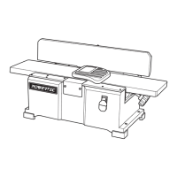
ATTACH FENCE SUPPORT
Figure 2-1
Turn the switch to OFF position and disconnect the
machine from power source.
• Use two socket head bolts and washers to lock the
fence support to the jointer.
• Insert locking plate assembly (E) into fence support (C).
Position locking plate so that two pins are against the
bottom edge of the fence support.
• Secure the locking plate in position with fence sliding
handle (F) and spacer.
INSTALL FENCE
Figure 2-2 and 2-3
• Use the four socket head bolts and washers to attach
fence (B) to Fence bracket assembly (D).
• Slide fence and bracket (B+D) over and onto dovetails
of support and locking plate (C+E). (Figure 2-3)
• Slide fence forward so that the fence contacts the
cutterhead guard. At this position the cutterhead is
completely covered by cutterhead guard.
• Install fence tilting handle (H) with spacer through right
link and thread into left link. (Figure 3)
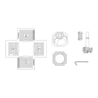
ATTACH DUST COLLECTION BAG
Refer to Figure 1 and 4
• Install the Dust Chute (I) by slip it over the Dust Port.
Tighten the screw on the Dust Chute (I).
• Insert Dust Bag Wire (L) through a small hole on the
sleeve of Dust Bag (J).
• Draw the open end of Dust Bag (J) sleeve through the
ring of Dust Bag Wire (L).
Figure 4 - 1
3
ASSEMBLY
Figure 2-1 - Attach Fence Support
C
E
F
B
Figure 2-2 - Assembling Fence and Fence Bracket
D
Socket Head Bolt
Figure 2-3 - Assembling Fence and Fence Bracket
F
Figure 3 - Attach Fence Assembly
Outward Stop
Shaft
Hex Nut
Limit Plate
H
Pin
WARNING
Socket
Head Bolt
Figure 4 - 2
slipping
the
the