Installation
31
Powerware
®
9150 User’s Guide
:
www.powerware.com
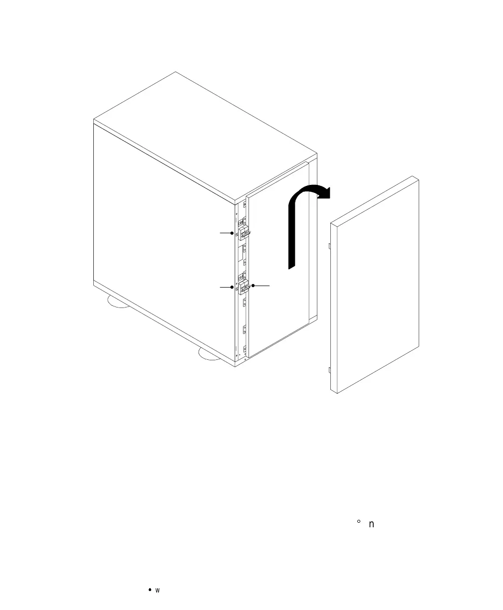
CB2
CB1 Safety
Wire
Figure 12. EBC Front Panel
5. Verify that the circuit breakers CB1 and CB2 are in the OFF
position on each battery cabinet.
6. Remove the cover plate on the rear of the UPS cabinet (see
Figure 13). Pull the battery connector out of the UPS, cut the
tie-wrap, and discard the cover plate.
Pull the battery cable from the rear of the battery cabinet and
plug it into the battery connector on the UPS rear panel. Rotate
the EBC conduit fitting into position (90
angle up).
Push the battery cable into the UPS and secure the EBC cover
plate to the UPS rear panel.