Operation
46
Powerware
®
9150 User’s Guide
:
www.powerware.com
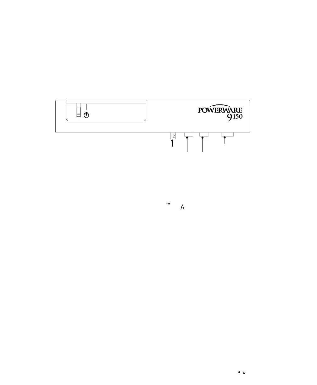
Computer and Alarm Connections
An interface for direct communication with your computer system is
supplied in the UPS. The interface consists of two RS-232 serial data
interfaces, four isolated alarm contacts, and remote emergency
power-off (REPO). These interfaces are located beneath the control
panel (see Figure 18).
REPO
9-Pin Port for RS-232 (Female) 9-Pin Port for RS-232 (Male)
15-Pin Relay Interface
|
X2
®
Figure 18. REPO and Serial Port Locations
Hardware Installation
Figure 19 shows the communication cables connected to the UPS. If you
have an optional ConnectUPS
É
SL Adapter, remove the mounting
bracket and reinstall with the adapter in position. Use the female 9-pin
UPS serial port for the serial power connector. Follow the instructions in
your ConnectUPS SL Operator’s Manual for configuration.