39
Powerware
®
9150 User’s Guide
:
www.powerware.com
CHAPTER 4
OPERATION
This chapter contains information on how to use the Powerware 9150,
including UPS shutdown, maintenance bypass operation, and UPS
communication.
Control Panel Functions
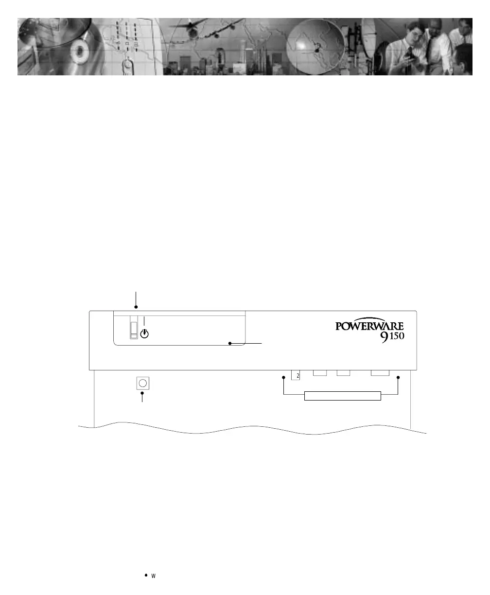
The control panel contains the UPS ON/OFF switch, the Battery Start
pushbutton, and the LED panel. The control panel shows the status of
the operation and generates an audible alarm (see Figure 14). The LED
panel contains the UPS indicators and the RESET pushbutton (see
Figure 15).
|
X2
Battery Start
UPSON/OFF
LED Panel
Communication Ports
®
Figure 14.Powerware9150 Control Panel